When you click on links to various merchants on this site and make a purchase, this can result in this site earning a commission. Affiliate programs and affiliations include, but are not limited to, the eBay Partner Network.
<table width="100%" align="center" class="tborder" id="post6232313" border="0" cellspacing="0" cellpadding="6"> <tbody> <tr valign="top"> <td class="alt1" id="td_post_6232313" style="border-right-color: rgb(41, 63, 92); border-right-width: 1px; border-right-style: solid;" itxtharvested="0" itxtnodeid="124">
Here is the Duraspark II directions and it plainly states to use the ballast resistor ( Pink wire)
This Duraspark II Ignition Harness is designed to connect the components in Ford electronic ignition systems using the “Blue Strain Relief” ignition module. It can be used with both the large cap and small cap early electronic distributors. 1. Disconnect the negative battery cable. 2. Mount the ignition module either on the firewall or inner fender. Connect the three pin and four pin ignition module connectors to the module. Note: This harness has ONLY been tested for the “Blue” and “Yellow” ignition modules. 3. Route the coil connector and distributor connector to their appropriate components, using caution not to run it over an exhaust header or manifold. Be sure to leave enough slack in the harness for engine torque. Slide the coil connector firmly onto the coil and plug-in the distributor connector. 4. Use the diagram on the next page as a guide to make the following connections. Connect the Red wire to the ignition hot side of the ballast resistor. Connect the Red/Green wire to the output side of the ballast resistor. 5. Next connect the white wire to the “I” terminal on the starter solenoid. Note: If the solenoid being used do es not have an “I” terminal, the white wire must be connected to the “S” terminal of the solenoid. 6. The yellow wire is the signal for a tachometer. If one is not being used, tape-up and stow this wire. 7. Reconnect the negative battery cable and test start the vehicle. <!-- google_ad_section_end -->
Like I mentioned, it's been a long time since I've installed a Duraspark ignition and I couldn't remember the exact details of it.
My inline 300 DS distributor is actually the DS II version with the larger cap (wider spaced spark plug wire terminals). I think the bigger cap looks much better than the small distributor cap.
conversion
There has been considerable talk about the Ford pink resistor wire over the years. The guys on Mustang Steves site concluded it needs to be bypassed to run the Duraspark II. I followed that advice on my old 68 Falcon 351W conversion years ago and drove the car for years that way before I sold it. I've followed this diagram for my current conversion as well.
I'd also recommend only buying a Motorcraft ignition module box, not the cheap repros. I got one on ebay last month.
conversion
There has been considerable talk about the Ford pink resistor wire over the years. The guys on Mustang Steves site concluded it needs to be bypassed to run the Duraspark II. I followed that advice on my old 68 Falcon 351W conversion years ago and drove the car for years that way before I sold it. I've followed this diagram for my current conversion as well.
I'd also recommend only buying a Motorcraft ignition module box, not the cheap repros. I got one on ebay last month.
I've been a member of Mustang Steve's forum since June, 2001. I've been to more than half the birthday bashes/Mustang get together he's had, annually, since 2004. I've even been to his house a couple of times.
This is a Duraspark wiring schematic Steve Wilkes (Mustang Steve) produced. You can find this drawing all over the internet.
One problem with the DS module is heat soak and the lack of air circulation to keep it cool to prevent it from melting the potting, of the electronics, out of the module case.
While my DS module/distributor aren't installed yet, I took some 5/16" diameter fuel hard line and cut three pieces 3/8" long. They will be used as stand-offs between the bottom of the module to the surface of the inner fender apron.
This will keep the bottom of the module from being mounted flat to the panel. With it spaced off the panel, air will be able to circulate ALL the way around it, not just partially around it.
When I get it installed, I can say my old '69 has a 'black' box in it.
Ah yes, Ultrastang. I remember you from there. Your Mustang Steve diagram is an older version. The current diagram on his site is the one I've linked that says "disconnect the pink resistor wire".
Good idea to space up the module for better cooling.
Ah yes, Ultrastang. I remember you from there. Your Mustang Steve diagram is an older version. The current diagram on his site is the one I've linked that says "disconnect the pink resistor wire".
Good idea to space up the module for better cooling.
I didn't pay attention to the diagram version when I copied the link. I just grabbed the first one that popped up on an Internet search.
Yep, on the Mustang forums, I'm 'ultrastang.' I didn't initially put the two together that you're the same guy from MS's forum. Now that I know who you are, "hello" fellow Mustanger and effie trucker!
There are lots of knowledgeable and good people willing to help at both Mustang Steve's forum, as well as this forum too.
I didn't go in to detail on my 'vestigation yesterday but I think with or without the pink wire it matters which ignition module you use. I believe with a Ford module you use the pink wire and with an aftermarket module you by-pass it. Double check me though Ultra.
I'd also recommend only buying a Motorcraft ignition module box, not the cheap repros. I got one on ebay last month.
You are exactly right Uni. The aftermarket modules have 1/3 to a 1/2 less electronics in them as the genuine Ford Motorcraft ones. I remember back in the day Ford actually came out with a poster for dealers to showcase by their retail counter so customers could SEE the internal difference. I am the one who mounted that poster to our retail counter.
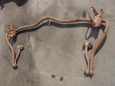
UPS had sent me a notice this morning that the '79 Bronco rear sway bar/bracket assembly I bought will be delivered tomorrow.
In the not too distant future, I'll find out if it's actually going to work on my F100. LOL (The guy buys a rear sway bar without knowing whether or not it'll even work). Yeah, that's right. That's how I roll.
It should look like this.
Sometimes things work out, sometimes they don't. It's just the chance you take in the pursuit of improvement.
UPS had sent me a notice this morning that the '79 Bronco rear sway bar/bracket assembly I bought will be delivered tomorrow.
In the not too distant future, I'll find out if it's actually going to work on my F100. LOL (The guy buys a rear sway bar without knowing whether or not it'll even work). Yeah, that's right. That's how I roll.
It should look like this.
Sometimes things work out, sometimes they don't. It's just the chance you take in the pursuit of improvement.
Also, you may just be Pioneering the way for many after you Ultra. that's what I call "taking one for the team".
Heck looks easy enough to fab up and make it work. When you have the right attitude that it takes to make things work one way or another.
Were on the same page of doing things.
Orich
The Bumpside trucks that did have a front sway bar are at a great disadvantage. Those sway bars were mounted to the inboard sides of the radius arms. If you initially had plans of running headers, you can forget it with that style sway bar --there's not enough clearance between the frame rails and the inboard mounted sway bar because that sway bar is right in the (explitive) way!
On the Dentside F100-F350s, Ford got it right. They designed a beefy front sway bar that was forward mounted of the radius arms and, the front end of the bar attached to the forward end of the frame rails.
They will bolt right up to a '65-'72 F100-F350, because the Bumpside front frame rails are the same width apart as the Dentside front frame rails. Headers are zero problem in conjunction with the Dentside front sway bar on the Bumps.
However, the rear of the truck becomes a problem when trying to adapt a Dentside rear sway bar. The problem is the rear frame rail width on the Dentsides flares outward from the back of the cab to the trailing ends of the rails under the bed. The width the Dentside rear frame rails flare out is 4" wider than the Bumpside rear frame rails.
This means there will be a difference of 2" per side that will have to be compensated for, either through a fabricated upper end link mount on the rear frame rail, fabricated spacers, fabricated offset end links or, possibly a combination of these things.
The other possible factor of it not working is the bow in the rear bar at the outer edges and the location of the forward arms of the bar for the end links. It MAY be that they will interfere with the narrower inset of the Bumps rear leaf springs (??). --don't know yet and only time will tell if this possibility is real.
I've seen and read about people installing the Dentside front sway bars on these trucks but, I've found no information on anyone installing the Dentside/Bronco rear sway bars on the Bumpsides.
If it works, I guess I'll be the 'hero.' If it doesn't work, I suppose I'll just be the village idiot.
I suppose if I was going to rate my intelligence, I'd say I'm probably at least in the top ten percentile of the smartest idiots around.
None of this matters on a F250 4x4... Lots of very nice F100's out there, w/2WD... but 4x4's get you stuck further from town... nothing like a good walk.
No explanation is necessary for those who understand, and none is possible for those who do not..
This Hennessey Takes the Expedition Tremor's Off-Roading Capability to the Next Level
Slideshow: The VelociRaptor Expedition gains a lift, upgraded suspension, Brembo brakes, and trail-ready equipment while retaining the stock 440-horsepower EcoBoost V6.
Rezvani's Latest Post-Apocalyptic Monster Is a Ford F-150 Raptor Underneath
Slideshow: Called the Fortress, the 850-horsepower pickup combines Raptor underpinnings with military-inspired features, survival equipment, and a starting price of $285,000.





 .
. </td> <td align="right" class="alt1" style="border-width: 0px 1px 1px 0px; border-style: solid; border-color: rgb(41, 63, 92);" itxtharvested="0" itxtnodeid="246">


 </td></tr></tbody></table>