


Bye Bye Front Drums

Thread Starter
|
Lead Driver


Joined: Apr 2011
Posts: 6,399
Likes: 40
From: El Dorado, Arkansas
Since my truck is a '69 model, and currently with its carbureted 240, it's just a 'dumb' system. My tool of choice to track down wires or wiring/continuity problems is this Fluke 77 III multi-meter.

Eventually, the carbed 240 (dumb) engine will be replaced by a more 'intelligent' '90 Mustang GT 5.0L H.O. fuel injected engine, controlled by a '92 5.0L Mustang GT Mass Air A9P EEC-IV engine processor.
When/if problems happen with a dumb engine, you just have to have a sense of the symptom to have an idea of what to begin to look at, to find the problem. Resolution may be quick and easy or, you may be on a wild goose chase of wasting time and throwing money at unnecessary parts before you actually find what's wrong to fix it.
An 'intelligent' (Ford fuel injected) engine has the advantage of a communications port in its main engine wiring harness that you can plug a code scanner into to quickly track down and identify any problems going on with the engine.
For this, I have more advanced tools for its diagnostics --an actual Ford Service Department Rotunda Super Star II code scanner.

If there's a problem between the EEC-IV engine processor, through the engine harness and to the engine sensors, I can connect the Rotunda 60-pin breakout box (BOB) to track down where the problem is.

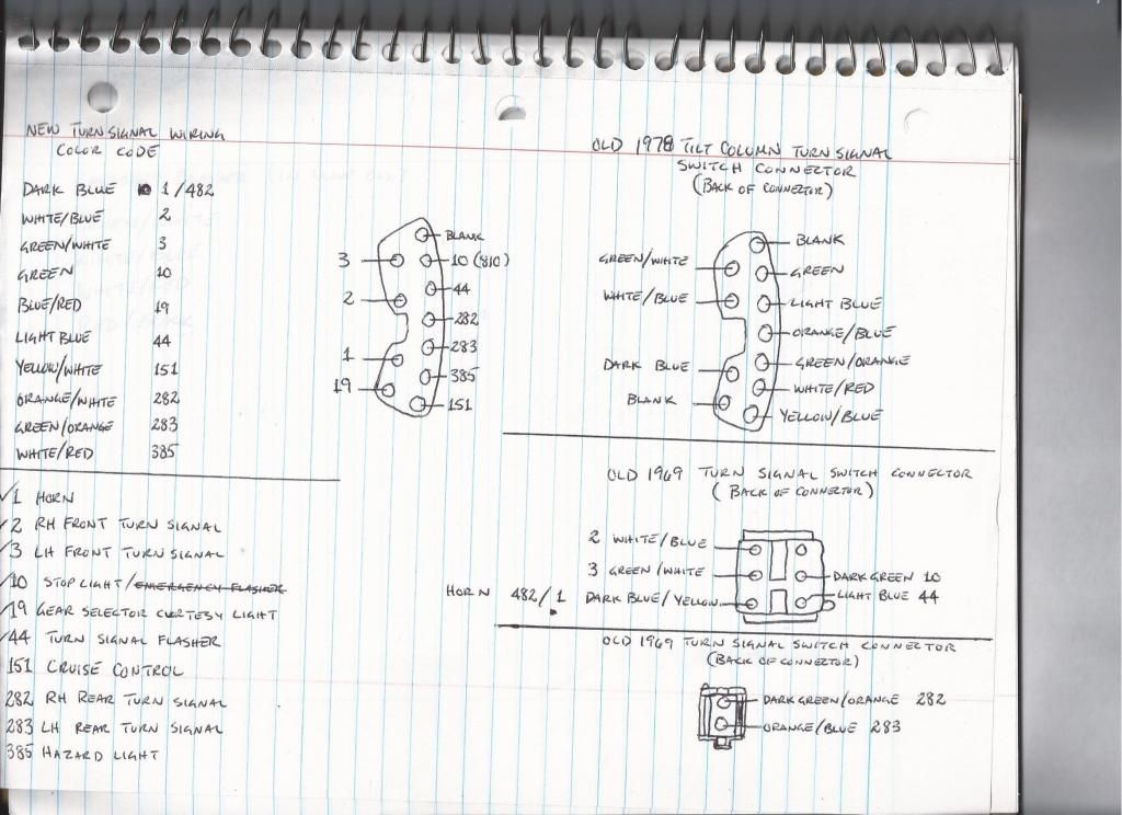
This is a rough sketch I made of the connectors, for the tilt column installation, and the identification of the wires/color codes I was working with.
As I had mentioned, I don't currently have the hazard switch, on the tilt column, tied into the circuit. The hazards still work off the switch in the glove box. --the yellow wire isn't hooked up because the cruise control module isn't currently installed.
Everything else on the column wiring is hooked up and works but, there's something screwy going on with the blinkers. When I push the turn signal lever up, the left side blinkers come on --and vise-versa. I've swapped the position of the signal wires and it doesn't correct the problem (???). This is just something I'll have to look at further to sort out what's going on with that.
On my old '69 fixed column, there was only one horn contact sticking up off the turn signal switch (Blue/Yellow wire) and one slip ring it contacted on the underside of the old steering wheel.
On the '78 column turn signal switch, there are two horn contacts (Dark Blue wire on one contact and a Yellow/White wire on the other contact --I bought the (tilt column) turn signal switch brand new from Bronco Graveyard --Shee-Mar, Inc. p/n SM61F). On the '79 donor truck wiring connector/pigtail, the wire color codes are Dark Blue and Yellow/Blue.
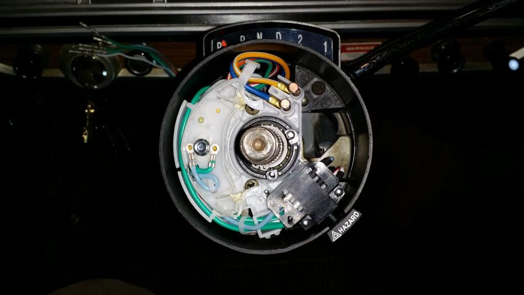
I didn't use both contacts for the horn. I used the contact on the turn signal switch closest to the center of the steering wheel hub --just like it was on the old '69 turn signal switch. The circuit comes up hot through the Dark Blue wire, through the contact, through one of the two slip rings on the Momo steering wheel adapter, through the horn button and then to ground inside the hub to energize the horns.
The cruise control I'll be installing came from the same '90 Mustang GT I pulled the 5.0L EFI engine from. The CC switches don't have 5 different wires going back to the module for each of the CC buttons. There are common wires that run between the switches in the steering wheel, and a ground and a hot that will go to the CC module. The hot doesn't send a 12v signal to the CC module for each button. Each button has a different resistance value that sends a signal to the module. The module knows what button is being pressed by the resistance value it receives. This is why 5 separate wires from the steering wheel/column to the module aren't needed.
These are some of the schematics I used to trace out circuits and try and identify wire colors:
http://www.fordification.com/tech/tilt.htm
http://www.fordification.com/tech/wi...ghts_81-85.jpg
http://www.fordification.com/tech/wi...orncircuit.jpg
http://www.fordification.com/tech/schematics_h.htm
http://fordification.net/tech/images...aster_5of9.jpg
http://fordification.net/tech/wiring.htm

Eventually, the carbed 240 (dumb) engine will be replaced by a more 'intelligent' '90 Mustang GT 5.0L H.O. fuel injected engine, controlled by a '92 5.0L Mustang GT Mass Air A9P EEC-IV engine processor.
When/if problems happen with a dumb engine, you just have to have a sense of the symptom to have an idea of what to begin to look at, to find the problem. Resolution may be quick and easy or, you may be on a wild goose chase of wasting time and throwing money at unnecessary parts before you actually find what's wrong to fix it.
An 'intelligent' (Ford fuel injected) engine has the advantage of a communications port in its main engine wiring harness that you can plug a code scanner into to quickly track down and identify any problems going on with the engine.
For this, I have more advanced tools for its diagnostics --an actual Ford Service Department Rotunda Super Star II code scanner.

If there's a problem between the EEC-IV engine processor, through the engine harness and to the engine sensors, I can connect the Rotunda 60-pin breakout box (BOB) to track down where the problem is.

This is a rough sketch I made of the connectors, for the tilt column installation, and the identification of the wires/color codes I was working with.

As I had mentioned, I don't currently have the hazard switch, on the tilt column, tied into the circuit. The hazards still work off the switch in the glove box. --the yellow wire isn't hooked up because the cruise control module isn't currently installed.
Everything else on the column wiring is hooked up and works but, there's something screwy going on with the blinkers. When I push the turn signal lever up, the left side blinkers come on --and vise-versa. I've swapped the position of the signal wires and it doesn't correct the problem (???). This is just something I'll have to look at further to sort out what's going on with that.
On my old '69 fixed column, there was only one horn contact sticking up off the turn signal switch (Blue/Yellow wire) and one slip ring it contacted on the underside of the old steering wheel.
On the '78 column turn signal switch, there are two horn contacts (Dark Blue wire on one contact and a Yellow/White wire on the other contact --I bought the (tilt column) turn signal switch brand new from Bronco Graveyard --Shee-Mar, Inc. p/n SM61F). On the '79 donor truck wiring connector/pigtail, the wire color codes are Dark Blue and Yellow/Blue.

I didn't use both contacts for the horn. I used the contact on the turn signal switch closest to the center of the steering wheel hub --just like it was on the old '69 turn signal switch. The circuit comes up hot through the Dark Blue wire, through the contact, through one of the two slip rings on the Momo steering wheel adapter, through the horn button and then to ground inside the hub to energize the horns.
The cruise control I'll be installing came from the same '90 Mustang GT I pulled the 5.0L EFI engine from. The CC switches don't have 5 different wires going back to the module for each of the CC buttons. There are common wires that run between the switches in the steering wheel, and a ground and a hot that will go to the CC module. The hot doesn't send a 12v signal to the CC module for each button. Each button has a different resistance value that sends a signal to the module. The module knows what button is being pressed by the resistance value it receives. This is why 5 separate wires from the steering wheel/column to the module aren't needed.
These are some of the schematics I used to trace out circuits and try and identify wire colors:
http://www.fordification.com/tech/tilt.htm
http://www.fordification.com/tech/wi...ghts_81-85.jpg
http://www.fordification.com/tech/wi...orncircuit.jpg
http://www.fordification.com/tech/schematics_h.htm
http://fordification.net/tech/images...aster_5of9.jpg
http://fordification.net/tech/wiring.htm
Postmaster
Joined: Nov 2012
Posts: 2,806
Likes: 8
From: Langley, BC
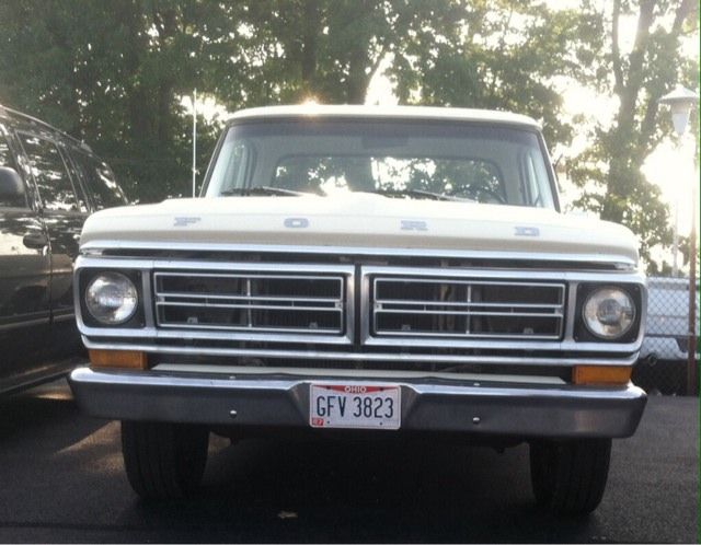
Funny that I was talking about a core support being painted the color of the body taking away from the appearance of the grille (unless the color of the body is black), and I found this on another truck forum.
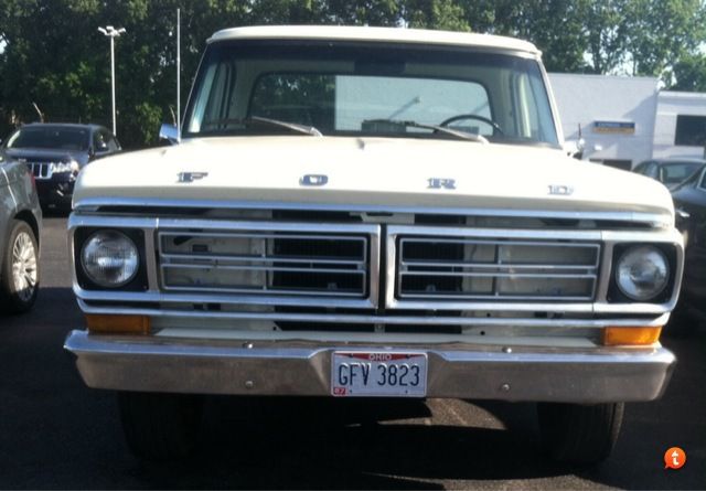
The guy knew something didn't look right with the front of his truck. It was pointed out the core support wasn't black and it was taking away from the grille.
Before and after. You can see how much difference it makes in your attention being drawn to the core support vs. noticing the grille. --the same would be true of brake drums painted some color other than black.
The guy knew something didn't look right with the front of his truck. It was pointed out the core support wasn't black and it was taking away from the grille.
Before and after. You can see how much difference it makes in your attention being drawn to the core support vs. noticing the grille. --the same would be true of brake drums painted some color other than black.


AsBPOJ2.jpgp
Thread Starter
|
Lead Driver
Joined: Apr 2011
Posts: 6,399
Likes: 40
From: El Dorado, Arkansas
Yep. Makes a BIG difference in what you do or don't notice.
Thread Starter
|
Lead Driver
Joined: Apr 2011
Posts: 6,399
Likes: 40
From: El Dorado, Arkansas
My original drum/drum pressure differential valve was mounted inside the left frame rail, right behind the manual steering gear box.
Since I've replaced the front drums with discs, I made a bracket to mount the new disc/drum combination brake valve to the top of the power steering gear box.
The original connector wiring, to the pressure differential switch, was too short to reach the brake valve switch in its new location. Again, I didn't want to cut the truck's original wiring so, what's a person to do?
I followed the wires back from the original switch connector and found it went back to a moulded male/female bullet terminal connector, beside the brake booster.
I dug around in some of my old brake valves and removed a switch connector/pigtail from one of them. I had an old backup light lying around, from a '67 Mustang, that had the same exact style moulded bullet connector on the end of it.
I clipped the connector off the backup light (I've seen a new bullet connector/pigtail like this at NAPA. It may be possible it would work. I think the bullet terminal is a .159" diameter).
Re-purposed parts. Brake pressure differential switch/pigtail on the left. Male/female bullet connector on the right.

Wire lengths staggered so the butt splices aren't directly side-by-side.

Connections crimped, soldered and heat shrink over the spliced connections.


Original switch connection near brake booster taken loose...

...'new' connector plugged in, and again, done without cutting any of the truck's original wiring.

Since I've replaced the front drums with discs, I made a bracket to mount the new disc/drum combination brake valve to the top of the power steering gear box.
The original connector wiring, to the pressure differential switch, was too short to reach the brake valve switch in its new location. Again, I didn't want to cut the truck's original wiring so, what's a person to do?
I followed the wires back from the original switch connector and found it went back to a moulded male/female bullet terminal connector, beside the brake booster.
I dug around in some of my old brake valves and removed a switch connector/pigtail from one of them. I had an old backup light lying around, from a '67 Mustang, that had the same exact style moulded bullet connector on the end of it.
I clipped the connector off the backup light (I've seen a new bullet connector/pigtail like this at NAPA. It may be possible it would work. I think the bullet terminal is a .159" diameter).
Re-purposed parts. Brake pressure differential switch/pigtail on the left. Male/female bullet connector on the right.

Wire lengths staggered so the butt splices aren't directly side-by-side.

Connections crimped, soldered and heat shrink over the spliced connections.


Original switch connection near brake booster taken loose...

...'new' connector plugged in, and again, done without cutting any of the truck's original wiring.


Cross-Country
Joined: May 2007
Posts: 64
Likes: 0
From: Huntsville, Alabama

I've been called OCD, but I don't know if I have the patience to do that, lol.
Thread Starter
|
Lead Driver
Joined: Apr 2011
Posts: 6,399
Likes: 40
From: El Dorado, Arkansas
My truck is nowhere close to perfect and without totally tearing it down and starting completely over, it's not going to be perfect.
In the areas I am working on, I try to make the components look as good as possible. If the detail in cleaning and painting parts is time consuming, oh well. The pay off for the extra time spent will come when the project is done. This requires the extra time put into it, in order to make that happen.
After all, this is what I bought the truck for in the first place --to eventually make it run and look really nice.
Cross-Country
Joined: May 2007
Posts: 64
Likes: 0
From: Huntsville, Alabama
Ultraranger,
I understand completely. My goal is to make my 72 run and drive good first, then worry about aesthetics, but that doesn't mean it cannot look nicer along the way as well. My first big project after I get my rusty bed replaced is going to be completely cleaning the engine compartment.
Gene
I understand completely. My goal is to make my 72 run and drive good first, then worry about aesthetics, but that doesn't mean it cannot look nicer along the way as well. My first big project after I get my rusty bed replaced is going to be completely cleaning the engine compartment.
Gene
FTE Stories
Ford Trucks for Ford Truck Enthusiasts

Top 6 Best Deals Available on New Fords & Lincolns Right Now
Brett Foote
This Hennessey Takes the Expedition Tremor's Off-Roading Capability to the Next Level
Verdad Gallardo
Top 10 Fords at 2026 Carlisle Ford Nationals
Joe Kucinski
3 Best / 3 Worst Parts of Modern Ford Ownership
Brett Foote
10 Amazing Upgrades That Solve Common Ford Truck Owner Headaches
Pouria Savadkouei
Every 2026 Ford Engine Explained
Brett Foote
10 Ugly Ford Trucks That We Still Kinda Love
Joe Kucinski
10 Things Every Truck Owner NEEDS (2026 Edition)
Michael S. Palmer
Rezvani's Latest Post-Apocalyptic Monster Is a Ford F-150 Raptor Underneath
Verdad Gallardo
Cargo Master
Joined: Nov 2005
Posts: 2,694
Likes: 45
From: La Ribera, Baja, Mexico
Well amigos, Gene has opened the subject of rusty bed... just so happens that yesterday, I picked up a used bed, for 2000 pesos (about $135 US), which I intend to clean up, and modify to fit over the rear mounted winch & gantry on my old truck. The plan is to make it appear as 'Normal' looking as possible. I will start my own thread, on Bed Restore, and photo document as it progresses.
Baja
Baja

Hotshot


Joined: Mar 2013
Posts: 14,255
Likes: 199
From: Phoenix, Az.
Well amigos, Gene has opened the subject of rusty bed... just so happens that yesterday, I picked up a used bed, for 2000 pesos (about $135 US), which I intend to clean up, and modify to fit over the rear mounted winch & gantry on my old truck. The plan is to make it appear as 'Normal' looking as possible. I will start my own thread, on Bed Restore, and photo document as it progresses.
Baja
Baja

Logistics Pro

Joined: Jun 2003
Posts: 3,928
Likes: 276
My original drum/drum pressure differential valve was mounted inside the left frame rail, right behind the manual steering gear box.
Since I've replaced the front drums with discs, I made a bracket to mount the new disc/drum combination brake valve to the top of the power steering gear box.
The original connector wiring, to the pressure differential switch, was too short to reach the brake valve switch in its new location. Again, I didn't want to cut the truck's original wiring so, what's a person to do?
I followed the wires back from the original switch connector and found it went back to a moulded male/female bullet terminal connector, beside the brake booster.
I dug around in some of my old brake valves and removed a switch connector/pigtail from one of them. I had an old backup light lying around, from a '67 Mustang, that had the same exact style moulded bullet connector on the end of it.
I clipped the connector off the backup light (I've seen a new bullet connector/pigtail like this at NAPA. It may be possible it would work. I think the bullet terminal is a .159" diameter).
Re-purposed parts. Brake pressure differential switch/pigtail on the left. Male/female bullet connector on the right.
Wire lengths staggered so the butt splices aren't directly side-by-side.
Connections crimped, soldered and heat shrink over the spliced connections.
Original switch connection near brake booster taken loose...
...'new' connector plugged in, and again, done without cutting any of the truck's original wiring.
Since I've replaced the front drums with discs, I made a bracket to mount the new disc/drum combination brake valve to the top of the power steering gear box.
The original connector wiring, to the pressure differential switch, was too short to reach the brake valve switch in its new location. Again, I didn't want to cut the truck's original wiring so, what's a person to do?
I followed the wires back from the original switch connector and found it went back to a moulded male/female bullet terminal connector, beside the brake booster.
I dug around in some of my old brake valves and removed a switch connector/pigtail from one of them. I had an old backup light lying around, from a '67 Mustang, that had the same exact style moulded bullet connector on the end of it.
I clipped the connector off the backup light (I've seen a new bullet connector/pigtail like this at NAPA. It may be possible it would work. I think the bullet terminal is a .159" diameter).
Re-purposed parts. Brake pressure differential switch/pigtail on the left. Male/female bullet connector on the right.
Wire lengths staggered so the butt splices aren't directly side-by-side.
Connections crimped, soldered and heat shrink over the spliced connections.
Original switch connection near brake booster taken loose...
...'new' connector plugged in, and again, done without cutting any of the truck's original wiring.
Hotshot
Joined: Mar 2013
Posts: 14,255
Likes: 199
From: Phoenix, Az.
Ford used that male/female plug in a zillion things Bobby. You might have one in your stash. Radios,lamps,wiring extensions,etc.
Logistics Pro
Joined: Jun 2003
Posts: 3,928
Likes: 276
Ha, you may be right, I may already have one. Thanks, I'll look around.

Thread Starter
|
Lead Driver
Joined: Apr 2011
Posts: 6,399
Likes: 40
From: El Dorado, Arkansas
1967 was the first year Ford went to tandem (split) brake systems from all the previous years single reservoir MCs.
On the '67 Ford brake valves, there was a single post connector/switch assembly.
Beginning in 1968-onward, Ford went to a double pin switch/connector.
The aftermarket valve Bobby has does not have the Ford designed single pin switch. That valve is based off a GM brake valve design. I don't know if the switch itself is also a direct copy of the original GM brake switch but, this is where I would look to find a connector/pigtail to plug into the switch.