


Bye Bye Front Drums
Cargo Master
Joined: Nov 2005
Posts: 2,694
Likes: 45
From: La Ribera, Baja, Mexico
Looks clean amigo, nice job. You've added the fan clutch I assume, as mine is a 67/72 and did not come with one in 67. How many blade is your fan? Mine is a Highboy, and I added the power steering, with the box mounted on the outside of the frame. With the pittman arm, indexed towards the outside also, the drag link had to be shortened to align with the knuckle arm. Worked out just fine, although I have more wheel travel to the right, than the left, but not much.
Good clean job, I like your work. are you going to add a fan shroud...??
bAJA
Good clean job, I like your work. are you going to add a fan shroud...??
bAJA
Thread Starter
|
Lead Driver


Joined: Apr 2011
Posts: 6,399
Likes: 40
From: El Dorado, Arkansas
Looks clean amigo, nice job. You've added the fan clutch I assume, as mine is a 67/72 and did not come with one in 67. How many blade is your fan? Mine is a Highboy, and I added the power steering, with the box mounted on the outside of the frame. With the pittman arm, indexed towards the outside also, the drag link had to be shortened to align with the knuckle arm. Worked out just fine, although I have more wheel travel to the right, than the left, but not much.
Good clean job, I like your work. are you going to add a fan shroud...??
bAJA
Good clean job, I like your work. are you going to add a fan shroud...??
bAJA
My '69 F-100 came with a fixed 18" 4-blade fan on the 240. I added the 19" Ford 7-blade clutch fan. The stamping on the fan blades reads D0SE-A. When I got the (new) fan clutch from the parts store to put on it, I specified a fan clutch for a 1979 Ford F-150 with a 300.
If you have the short shaft water pump, it's going to set the clutch fan further back from the radiator than where the placement of the fixed blade fan will be. --however, I live in hot, humid (in the summer time) south Arkansas and this didn't cause any cooling or overheating problems on my truck. Now, that I've installed the long shaft water pump, the clutch fan is much closer to the radiator.

As far as I know, my truck didn't come with a fan shroud. If it did, it was long gone before I bought the truck nearly 4 years ago.
After I get all these recent changes implemented on my truck, that I'm currently working on, the only major accessory I'll lack is A/C. Eventually, A/C will be added too.
My uncle had given me a Bumpside radiator core support with the large front opening for a super cool radiator (not installed yet). I'll likely (eventually) add a modern cross-flow aluminum radiator and electric fan. --I already have a 130 amp Ford 3G alternator so, the added amperage load of an electric cooling fan won't be a problem for the electrical system to handle.
The downside to being meticulous with the finish and detail of the components is it drags out the length of time it takes to get the swap over done. If I had just slapped the new stuff onto the existing dirty stuff, I would probably have been done by now and had the truck back up and running a few weeks ago.
The upside with the attention to detail though, is it looks more professional and has a lot nicer looking end result, when completed.
Thread Starter
|
Lead Driver
Joined: Apr 2011
Posts: 6,399
Likes: 40
From: El Dorado, Arkansas
I just got through making the two steel spacers that will go on the small PS bracket that bolts to the left side of the timing cover. --I had to move the PS pump forward so its pulley would line up with the forward most pulley grooves of the water pump and harmonic balancer, instead of the middle groove.
Now, I get to take the spacers back off and paint them. I need to go tomorrow and get some longer 5/16"-18 bolts. I used a couple of 5/16" Allen bolts to temporarily fit things up, to make sure it was sturdy and everything would line up.


Now, I get to take the spacers back off and paint them. I need to go tomorrow and get some longer 5/16"-18 bolts. I used a couple of 5/16" Allen bolts to temporarily fit things up, to make sure it was sturdy and everything would line up.


Cargo Master
Joined: Nov 2005
Posts: 2,694
Likes: 45
From: La Ribera, Baja, Mexico
I like what you have done, and the way you've done it. With the recent motor upgrades to my 300, I feel that it is producing more heat to go with the increased howspower. I have purchased an aluminum 4 core radiator, and 16" electric fan. I hope that this will solve any issue with my cooling that may arise. Living in Southern Baja, we have summer days, with temps in the mid 90's and a few days in the 100's.. So, we have some warm weather to deal with. Photos of the install when I get to Baja to do it.. Meanwhile, enjoy your ride..
Baja
Baja
Thread Starter
|
Lead Driver
Joined: Apr 2011
Posts: 6,399
Likes: 40
From: El Dorado, Arkansas
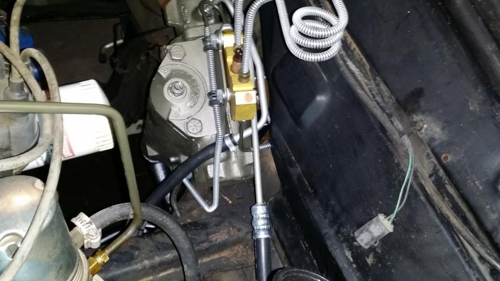
After having to take a couple of detours, in getting the water pump and power steering pump squared away, I'm finally back to where I left off with the brake lines.
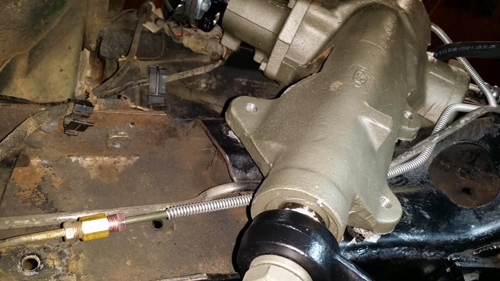
The line with the 7/16"-24 fitting on it is the original line/fitting going to the rear brakes. This is the location where this line had tied into the original drum/drum pressure differential valve that was previously mounted here. The green looking line is the new brake line I made coming from the disc/drum brake valve, that I mounted to the top of the power steering gear box.

The new (red) 7/16"-24 inverted flare nut and the new inverted flare coupling nut (Edelmann 123400 302 x 4) to tie the new line into the old line.
The red Sharpie mark indicates where I have to cut the excess tubing off. Looks like I had figured it pretty close.

Armor Guard to protect the line.

Armor Guard and new 7/16"-24 fitting slid on and in the process of double flaring the end of the tube.
Boom! Just like that.
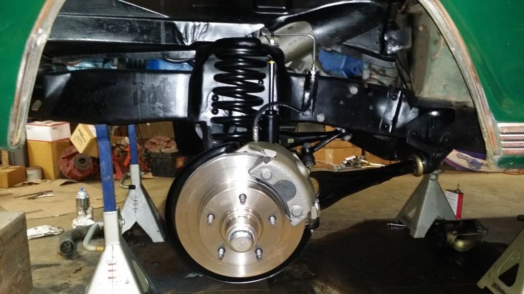
View from underneath.

View from engine bay.

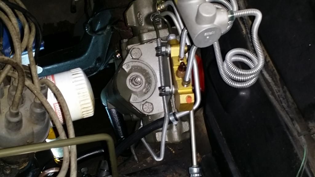
The line with the 7/16"-24 fitting on it is the original line/fitting going to the rear brakes. This is the location where this line had tied into the original drum/drum pressure differential valve that was previously mounted here. The green looking line is the new brake line I made coming from the disc/drum brake valve, that I mounted to the top of the power steering gear box.

The new (red) 7/16"-24 inverted flare nut and the new inverted flare coupling nut (Edelmann 123400 302 x 4) to tie the new line into the old line.
The red Sharpie mark indicates where I have to cut the excess tubing off. Looks like I had figured it pretty close.

Armor Guard to protect the line.

Armor Guard and new 7/16"-24 fitting slid on and in the process of double flaring the end of the tube.

Boom! Just like that.

View from underneath.


View from engine bay.


Thread Starter
|
Lead Driver
Joined: Apr 2011
Posts: 6,399
Likes: 40
From: El Dorado, Arkansas
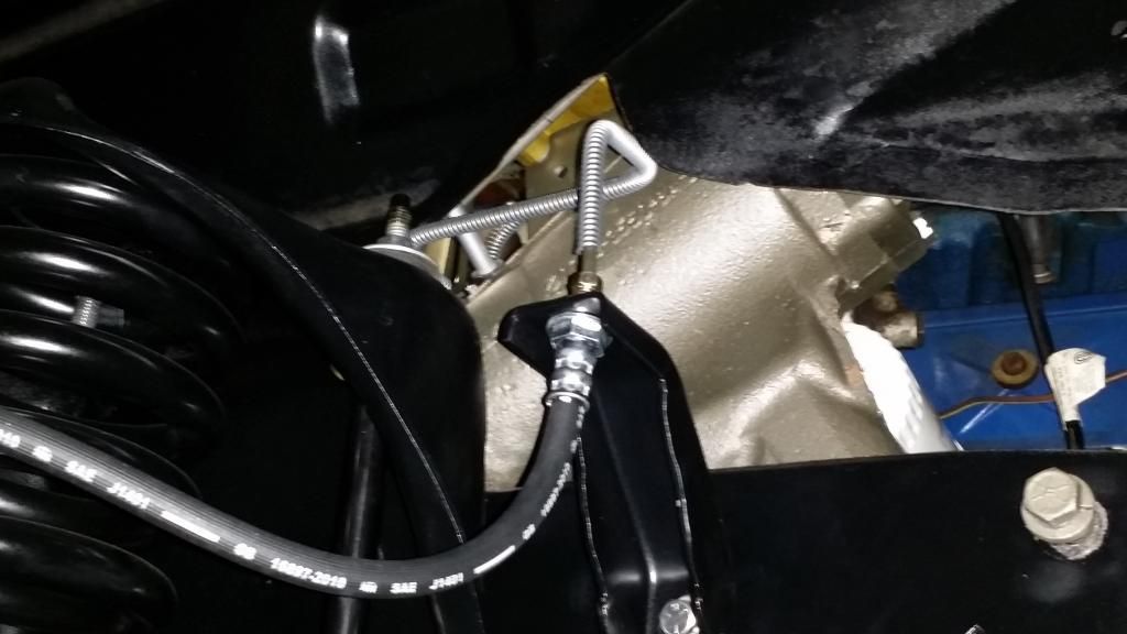
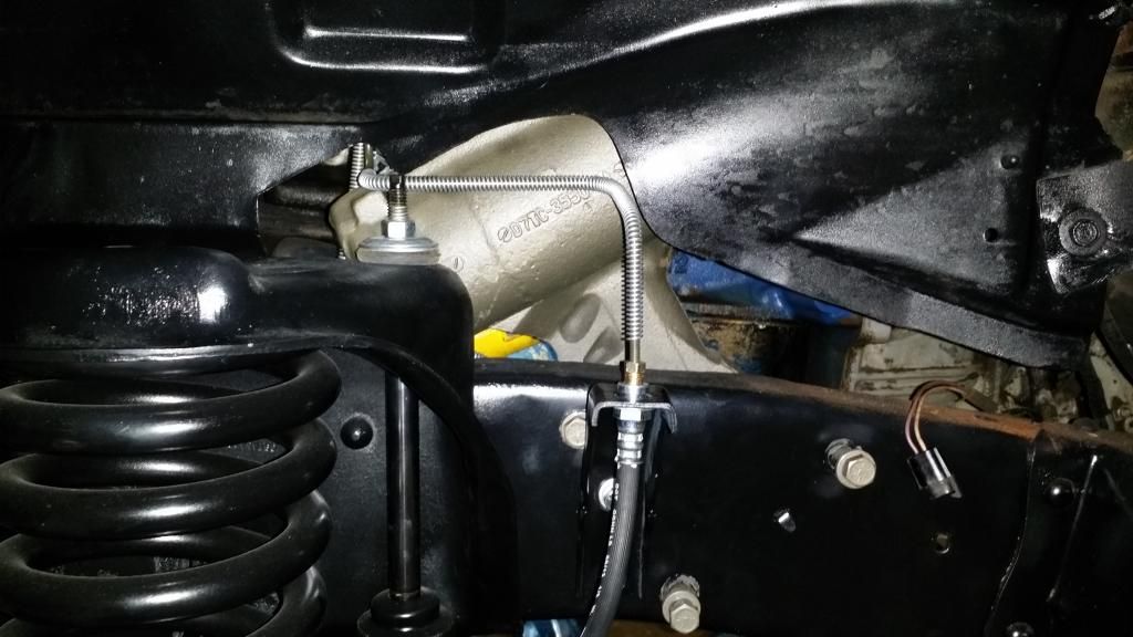
I got the line made from the brake valve out to the left front caliper hose.
Your basic straight piece of 3/16" brake tubing.
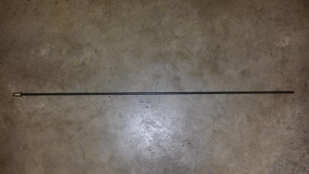
At top, a piece of 10 ga. Romex solid copper electrical wire bent as a template to make the actual line by.

Hard line installed.


Your basic straight piece of 3/16" brake tubing.

At top, a piece of 10 ga. Romex solid copper electrical wire bent as a template to make the actual line by.


Hard line installed.


Logistics Pro


Joined: Jun 2003
Posts: 3,928
Likes: 276
FTE Stories
Ford Trucks for Ford Truck Enthusiasts

Top 10 Fords at 2026 Carlisle Ford Nationals
Joe Kucinski
3 Best / 3 Worst Parts of Modern Ford Ownership
Brett Foote
10 Amazing Upgrades That Solve Common Ford Truck Owner Headaches
Pouria Savadkouei
Every 2026 Ford Engine Explained
Brett Foote
10 Ugly Ford Trucks That We Still Kinda Love
Joe Kucinski
10 Things Every Truck Owner NEEDS (2026 Edition)
Michael S. Palmer
Rezvani's Latest Post-Apocalyptic Monster Is a Ford F-150 Raptor Underneath
Verdad Gallardo
Top 10 Most Expensive Ford Trucks Ever Sold on Bring a Trailer
Joe Kucinski
2027 Ford Super Duty Buyer's Guide (Every Model, Engine, & Package)
Brett FooteCargo Master
Joined: Nov 2005
Posts: 2,694
Likes: 45
From: La Ribera, Baja, Mexico
The muffler shops, here in Baja, use the wire for the same idea... I replaced all the brake lines on my truck, while we had the cab off. Sure made it easy. Is the spiral line shield you used galvanized? If not, it would rust right away here close to the ocean. Our joke is that even "Plastic Rusts" in Baja. Living close to the ocean has its advantages for fishing, but not for anything metal. I like very much how 'clean' your mods are turning out... I am inspired to do some on my old truck.. just as clean.
Baja
Baja
Thread Starter
|
Lead Driver
Joined: Apr 2011
Posts: 6,399
Likes: 40
From: El Dorado, Arkansas
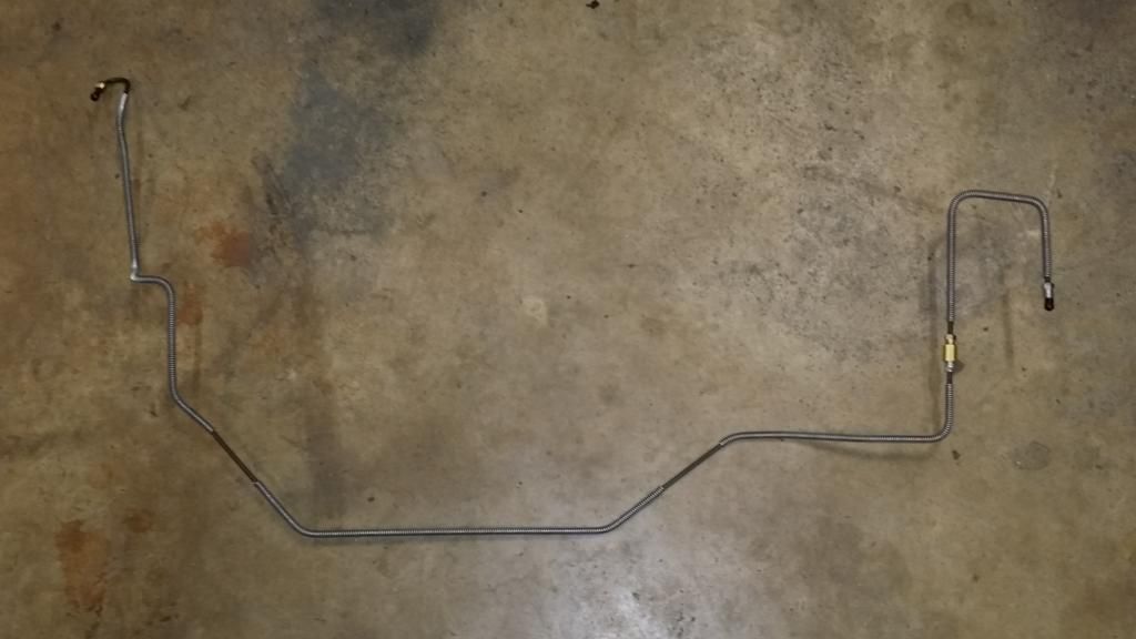
I measured out the bends I made for this line on an '80 Mercury Monarch 9-inch rear end housing. It originally had drum brakes but I converted it to '94-'04 11-5/8" Cobra rear discs.
Before.

It was easier making the line for the rear end housing, since it wasn't under a vehicle.


After.

The muffler shops, here in Baja, use the wire for the same idea... I replaced all the brake lines on my truck, while we had the cab off. Sure made it easy. Is the spiral line shield you used galvanized? If not, it would rust right away here close to the ocean. Our joke is that even "Plastic Rusts" in Baja. Living close to the ocean has its advantages for fishing, but not for anything metal. I like very much how 'clean' your mods are turning out... I am inspired to do some on my old truck.. just as clean.
Baja
Baja
The Armor Guard is coated. We don't get a lot of snow here in south Arkansas so, we don't have all the salt on the highways in the winter time, like they do up north and, I'm 400 + miles from the Gulf so, no danger of salty air mist corroding things around here.
Thread Starter
|
Lead Driver
Joined: Apr 2011
Posts: 6,399
Likes: 40
From: El Dorado, Arkansas
FINALLY! (and the angels sang --ahhhhh! ...that was the angel singing sound effect there).
I just got the last hard line completed a few minutes ago. It was just a little too long to be able to snake it around everything to get it into place. I had to break it on the right side and install a 3/16" inverted flare union (Edelmann 123300) and a pair of 3/16"-24 inverted flare fittings to be able to install it.
I'm glad this phase is finally behind me.

Thread Starter
|
Lead Driver
Joined: Apr 2011
Posts: 6,399
Likes: 40
From: El Dorado, Arkansas
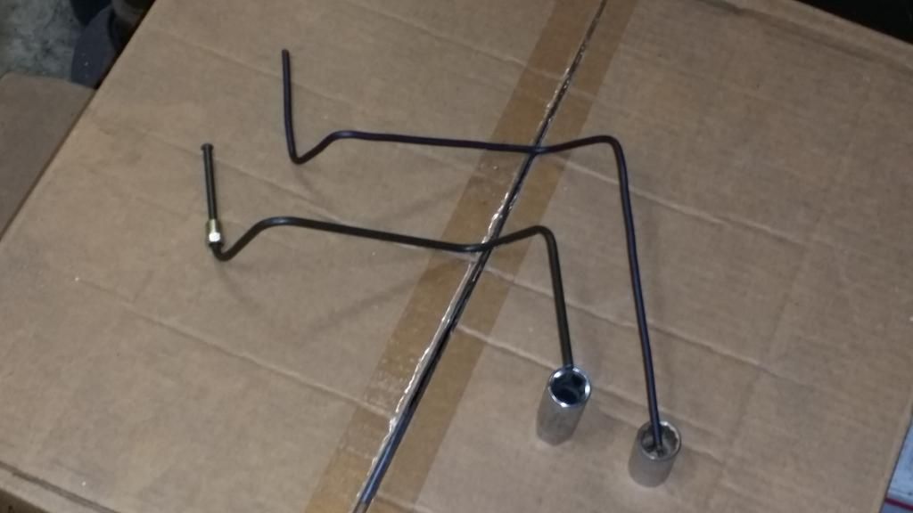
Here are some tips I use for fabricating brake tubing that I'll pass along to anyone that may be contemplating making their own lines.
Measuring out the bends and offsets for the lines is the best way to make accurate lines. However, trying to measure out the bends for lines on an assembled vehicle can be very difficult, with all the obstructions in the way.
That leaves the other alternative --a bend template, and this is the method I used to make the brake lines for this recent installation.
I used a simple 18" long piece of Romex solid copper electrical wire.

Start with the object you will be running the line from and work your way toward the object the line will be going to. In this example, I was running the line from the brake valve (mounted on top of the PS gear box) out to the right front caliper.
Since this was the longest run of the lines I made, it's obvious an 18" long piece of copper wire (the bend template) would not cover this entire distance, in one run --which was a span of about a 38" and a height of about 19".
I placed one end of the bend template in the port of the valve and then began forming the shape that I wanted the actual hard line to follow. ...but, an 18" template will only go so far...
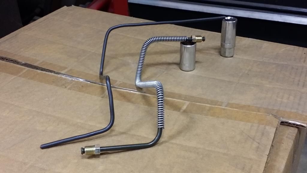
Once you have the first run that the length of the template will cover, take a piece of tape and stick it to the vehicle, where the very end of the template lands and make a mark perpendicular to the end of the template (if your template is running horizontally, make a vertical mark on the tape and vise-versa).


Make a small orientation mark on your tubing. This mark should be parallel with the tubing and pointed toward the ceiling, when you place the tubing into the bender.

After you start making bends in a line, it's very easy to loose track of what is up, down, left or right. Without a reference to the tube's orientation, it's easy to zig when you should have zagged.
After you've made the first run with the template, mark your chassis with the tape and marker (as shown above) where the end of the template stopped. Put your tubing in the bender, orientation mark of the tubing facing up, and bend the tubing by following the shape of your template.
Mark your tubing where the end of the first template run stopped (if the tubing run is going to be one that's longer than your template --this is going to be the next starting reference for the template when you pick back up for the next run of bends on the tubing).
Straighten the template back out. Picking back up where your reference mark is (the tape on the chassis with the mark on it), begin forming the template for the next series of bends from that point on-ward.
At the end of that run, put another piece of tape on the chassis and mark where the second template run ended, take the template, line it up with the reference mark on the tubing where you previously left off, then, bend the tubing following the next series of template bends, Mark your tubing where the template ended, and so on....
A template that's much over 18" is difficult to handle when you're trying to get a long length of tubing in the bender, level the tubing, orienting it, trying to hold the template in place and trying to bend the tubing while following along with the template. --In tight confines on a vehicle, an 18" template may be too long and may be better to use a shorter one --around 12".
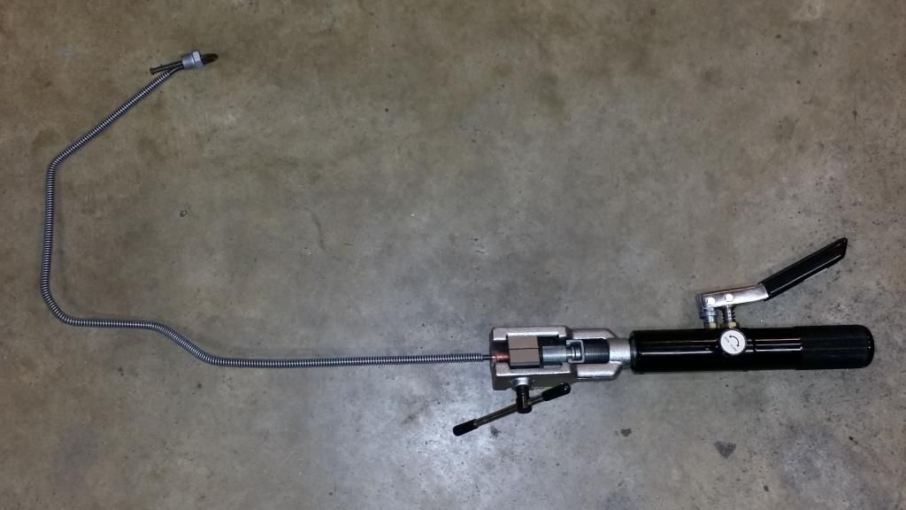
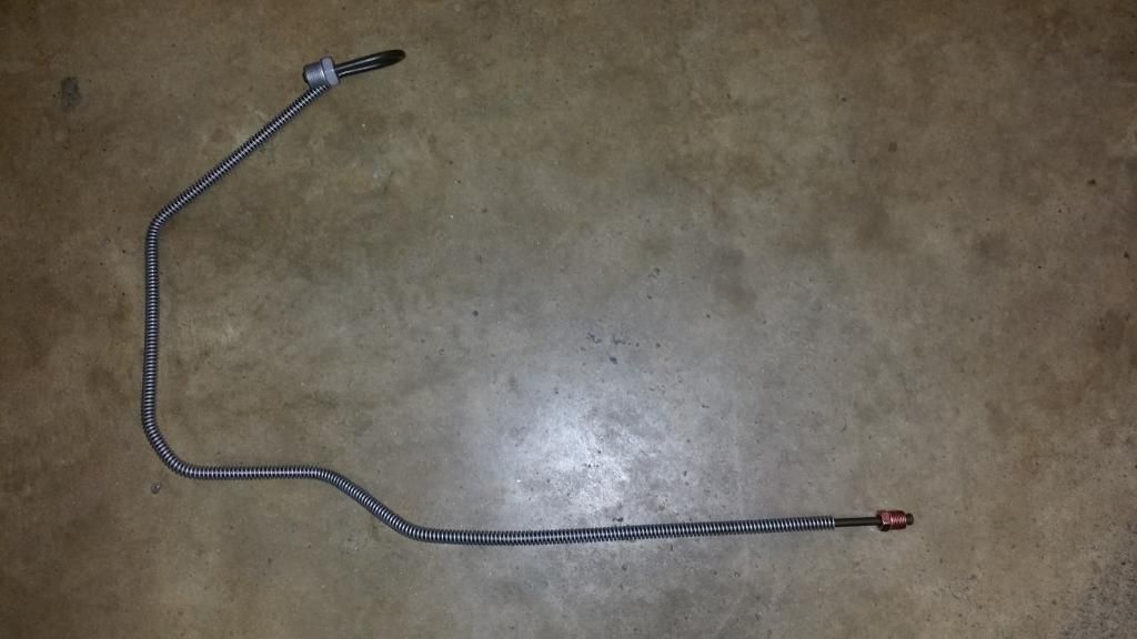
Example of the bend template used to make a short line --this line was a short run going from the brake valve out to the flexible hose on the left front caliper.
One long, continuous template to make this line, in one shot, would have been unwieldy to handle, and the bends would have been really sloppy, without breaking it down into (3) separate template runs to produce one long hard line.

Measuring out the bends and offsets for the lines is the best way to make accurate lines. However, trying to measure out the bends for lines on an assembled vehicle can be very difficult, with all the obstructions in the way.
That leaves the other alternative --a bend template, and this is the method I used to make the brake lines for this recent installation.
I used a simple 18" long piece of Romex solid copper electrical wire.

Start with the object you will be running the line from and work your way toward the object the line will be going to. In this example, I was running the line from the brake valve (mounted on top of the PS gear box) out to the right front caliper.
Since this was the longest run of the lines I made, it's obvious an 18" long piece of copper wire (the bend template) would not cover this entire distance, in one run --which was a span of about a 38" and a height of about 19".
I placed one end of the bend template in the port of the valve and then began forming the shape that I wanted the actual hard line to follow. ...but, an 18" template will only go so far...
Once you have the first run that the length of the template will cover, take a piece of tape and stick it to the vehicle, where the very end of the template lands and make a mark perpendicular to the end of the template (if your template is running horizontally, make a vertical mark on the tape and vise-versa).


Make a small orientation mark on your tubing. This mark should be parallel with the tubing and pointed toward the ceiling, when you place the tubing into the bender.

After you start making bends in a line, it's very easy to loose track of what is up, down, left or right. Without a reference to the tube's orientation, it's easy to zig when you should have zagged.
After you've made the first run with the template, mark your chassis with the tape and marker (as shown above) where the end of the template stopped. Put your tubing in the bender, orientation mark of the tubing facing up, and bend the tubing by following the shape of your template.
Mark your tubing where the end of the first template run stopped (if the tubing run is going to be one that's longer than your template --this is going to be the next starting reference for the template when you pick back up for the next run of bends on the tubing).
Straighten the template back out. Picking back up where your reference mark is (the tape on the chassis with the mark on it), begin forming the template for the next series of bends from that point on-ward.
At the end of that run, put another piece of tape on the chassis and mark where the second template run ended, take the template, line it up with the reference mark on the tubing where you previously left off, then, bend the tubing following the next series of template bends, Mark your tubing where the template ended, and so on....
A template that's much over 18" is difficult to handle when you're trying to get a long length of tubing in the bender, level the tubing, orienting it, trying to hold the template in place and trying to bend the tubing while following along with the template. --In tight confines on a vehicle, an 18" template may be too long and may be better to use a shorter one --around 12".
Example of the bend template used to make a short line --this line was a short run going from the brake valve out to the flexible hose on the left front caliper.
One long, continuous template to make this line, in one shot, would have been unwieldy to handle, and the bends would have been really sloppy, without breaking it down into (3) separate template runs to produce one long hard line.

Thread Starter
|
Lead Driver
Joined: Apr 2011
Posts: 6,399
Likes: 40
From: El Dorado, Arkansas
After 4 trips to the parts store today to get belts for the power steering pump and the alternator, I finally got a belt for the power steering pump that fits and a belt for the alternator that ALMOST fits. It was just a little too short. --what a pain! That means at least one more trip back to the parts store and hopefully zero in on the needed length belt for the alternator. (Well, actually, I'm going to install dual belts on the alternator).
I did get the power steering pump primed. I poured the type F fluid in and slowly turned the pump over with a 3/8" hex bit, driven by my 3/8" angle drill. I was watching down the filler neck as I slowly started turning the pulley with the drill motor. I couldn't believe how fast it sucked the fluid down in just a few revolutions at really slow speed.
No wonder so many people burn their new pumps up when they just install them, pour the fluid in and then just fire the engine up.
The drill motor method is good because you can keep the RPMs down and actually see the air purging from the reservoir, as the fluid level drops, to know when to stop and top the reservoir back off, before proceeding any further.

Hotshot

Joined: Mar 2013
Posts: 14,255
Likes: 199
From: Phoenix, Az.
Super nice work Steve. I like the attention to detail. Lines perfectly horizontal whenever possible. I bet you're like me always putting in the srews at the same finished angle on things like house light switch covers.
On the belts Ford measured on the inside diameter but I believe the aftermarket measured the O.D. I.E around the top of the pulleys. And I know you know but I'll say this for the rest of the readers. Make sure both those alternator belts are a "matched set". They have to have been cut from the same original belt casing and marked as such. If not one will end up tight and one floppin' a little right next to it.
On the belts Ford measured on the inside diameter but I believe the aftermarket measured the O.D. I.E around the top of the pulleys. And I know you know but I'll say this for the rest of the readers. Make sure both those alternator belts are a "matched set". They have to have been cut from the same original belt casing and marked as such. If not one will end up tight and one floppin' a little right next to it.
Thread Starter
|
Lead Driver
Joined: Apr 2011
Posts: 6,399
Likes: 40
From: El Dorado, Arkansas
Super nice work Steve. I like the attention to detail. Lines perfectly horizontal whenever possible. I bet you're like me always putting in the srews at the same finished angle on things like house light switch covers.
On the belts Ford measured on the inside diameter but I believe the aftermarket measured the O.D. I.E around the top of the pulleys. And I know you know but I'll say this for the rest of the readers. Make sure both those alternator belts are a "matched set". They have to have been cut from the same original belt casing and marked as such. If not one will end up tight and one floppin' a little right next to it.
On the belts Ford measured on the inside diameter but I believe the aftermarket measured the O.D. I.E around the top of the pulleys. And I know you know but I'll say this for the rest of the readers. Make sure both those alternator belts are a "matched set". They have to have been cut from the same original belt casing and marked as such. If not one will end up tight and one floppin' a little right next to it.
Here's one; I detest tires that are put on a wheel with the lettering (black or white letter) where nothing is indexed on the tire to the wheel's center cap --if the center cap has a logo or such on it or, referenced off the valve stem.
To me, a wheel with a logo center cap should have the letters of the tire's brand at the top and the tire name/series at the bottom, in relation to the center cap or valve stem.
Attention to simple details like this makes the difference between a mediocre vehicle and one that stands out head and shoulders above the rest (if a truck can have a head and shoulders).