When you click on links to various merchants on this site and make a purchase, this can result in this site earning a commission. Affiliate programs and affiliations include, but are not limited to, the eBay Partner Network.
The weather has been hot and humid here and put a bit of a damper on progress with the transmission but, I got the valve body apart and removed the separator plate.
The 4R70W doesn't require spending any money on buying a shift kit. There's a simple procedure known as the 'J-Mod' that drastically improves the shift firmness and rapid engagement of the clutches when the transmission up shifts or down shifts.
This promotes longer clutch life and reduces transmission fluid temperatures.
The J-Mod is named after one of the Ford engineers (Jerry Wroblewski) that designed the 4R70W transmission. In a document, he spec'd certain holes in the separator plate to be opened up to given diameters, and the deletion of a couple of accumulator springs, for the enhanced shifting performance upgrade.
Earlier model 4R70W transmissions (pre-'98) will require more holes (11 of them) to be opened up in the separator plate. On my '98 model, it requires 6 holes to be modified --five holes will be drilled out to 7/64" and one hole opened up to 3/32".
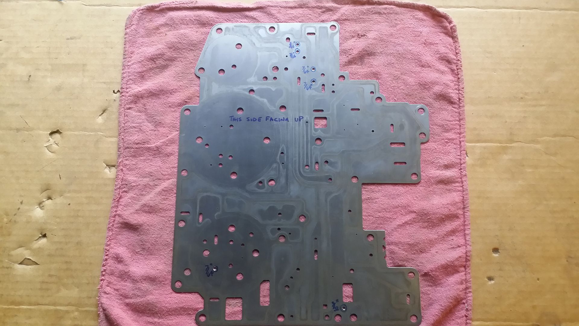
Here, I've located the specified holes to be opened up. I circled each hole and I wrote the diameter to drill them out to, out beside each of the holes. --I triple checked my locations and drill diameters against the diagram in the J-Mod instructions. --a screw up here of drilling the wrong hole or, drilling it too big, means having to buy another complete VB assembly, since the separator plate isn't available by itself.
The circled areas on the VB are the locations where the check ***** (8 of them) go back into --they are all the same diameter.
Years ago, I used to work at a chemical mill. There was miles of process lines with many orifice plates at various locations, between the pipe joints, to control fluid flow/volume through the lines.
The orifice plate openings had a sharp edge on the upstream side of the hole, in the plate and, a beveled (tapered) edge on the downstream side of the hole. The bevel on the downstream side of the hole greatly reduces turbulence of the fluid flow, as it passes through the opening of the orifice.
Non-beveled hole and resultant turbulence as the fluid flows through the hole to the downstream side.
Passage with squared off edges on both sides of the hole.
Passage with tapered opening on the downstream side of hole.
With this in mind, I decided I would apply this thought process to drilling the holes in the transmission separator plate.
My initial markings on the plate were on the downstream (transmission) side of it. It was obvious to me if I drilled through the plate from this side, it would leave a ridge on the upstream (pan side) side of the plate that would need to be de-burred.
After thinking about it, it made more sense to drill from the upstream (pan) side of the plate, where the bit would exit on the downstream (transmission) side of it, remove the burr and slightly bevel the opening on the downstream side of the plate, all in one whack.
Just to keep everything straight and the proper holes to be located on the other side of the separator plate, I inserted a bread tie through the hole (one hole at a time to reference the correct location), from the initial marked side, and I marked and labeled the holes on the other side.
Initial side of plate marked. This side of the plate will go up against the transmission case.
Holes re-marked on opposite side of plate. The plate will be drilled from this side. This side of the plate will be facing toward the filter/inside of the pan.
The J-Mod to the separator plate is complete. (5) of the holes were drilled to 7/64" and (1) was drilled to 3/32".
After I drilled the holes, there was, of course, a burr around each hole on the exit side. For the 7/64" holes, I took a drill bit twice that diameter (7/32") and turned it in the holes with my fingers.
This removed the burrs and simultaneously beveled the openings --just what I was after.
On the 3/32" hole, I used a drill bit that was twice as big as it (3/16") to de-burr/bevel that hole.
The shiny rings around the modified holes shows the slight bevel around them.
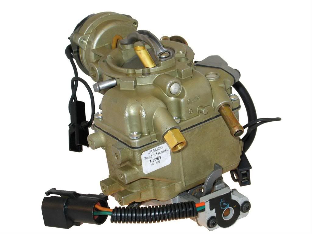
Check out this sexy beast. It's a Carter YFA carburetor that was on a 300 from an '80s Bullnose Ford pickup.
...and there's the TPS (Throttle Position Sensor) on the end of the throttle plate shaft.
The 4R70W transmission controller I have needs an input from the throttle plate to determine if the engine is at idle, WOT or, at some angle somewhere in between.
I don't know if this will work on my 240 but, my theory is IF the TPS throttle/base plate from the Carter YFA carburetor will swap in place of the base plate on my 240's YF carburetor, then I will have a TPS signal input for the Baumann transmission controller I have for my 4R70W transmission.
A better view of the TPS on the throttle base plate.
....and if the throttle plate w/TPS won't transfer over to my existing Carter YF, it isn't any great financial loss, since the carburetor was only $10.00 bucks.
Does that TPS pass on a voltage signal or a resistance signal? And what kind of signal does the controller require?
The TP sensor on the Carter YFA carburetor looks to be the same (or, VERY similar) as the TPS on the throttle body of the 5.0L H.O. EFI engine that'll eventually go into my truck.
The TPS uses a 0-5v signal, with the higher end being WOT, on a 5.0L engine with an EEC-IV engine processor.
With the Baumann transmission controller, I'm not sure if it's voltage based or resistance based. I would have to look back at the Baumann manual to be sure.
Sorry to be the bearer of bad news. The Bull nose throttle plate may not work on your existing carb. On your carb you have the same three screws that I see around the throttle plate. But this Bull nose plate has a 4th screw a little farther away from the other 3 at about 6:00 in you pic below. Whether or not this extra 4th mounting point is actually necessary you can figure out.
Sorry to be the bearer of bad news. The Bull nose throttle plate may not work on your existing carb. On your carb you have the same three screws that I see around the throttle plate. But this Bull nose plate has a 4th screw a little farther away from the other 3 at about 6:00 in you pic below. Whether or not this extra 4th mounting point is actually necessary you can figure out.
There are (4) screws in each base but, I'm not sure if the TPS throttle plate from the YFA will swap over onto my Carter YF, primarily because the later YFA is an auto choke and my YF is a manual choke. --linkages and such are different. ....it's been too hot here anyway to fool with it much to see what will or won't work.
At any rate, it isn't a great loss if it won't swap over. The fuel injected 5.0L engine, that will eventually go in the truck, is setup with a TPS on the 70mm Edelbrock/BBK throttle body that will definitely work with the transmission controller.
Rezvani's Latest Post-Apocalytic Monster Is a Ford F-150 Raptor Underneath
Slideshow: Called the Fortress, the 850-horsepower pickup combines Raptor underpinnings with military-inspired features, survival equipment, and a starting price of $285,000.