








WickidPissa Build Thread

Thread Starter
|
Elder User
Joined: Mar 2013
Posts: 844
Likes: 0
From: Dirty Water
Tailgate:
Been too crappy out to safely paint - project's on hold until nice weather unfortunately.
Courtesy Light Module:
Broke out the breadboard last night and grabbed some parts from radio shack - created a simple module that when triggered by a lock or unlock (pulse to ground), activates a 30 second closed circuit. Ordered 4 relays for the individual light circuits, just a matter of building the unit and installing now...
Been too crappy out to safely paint - project's on hold until nice weather unfortunately.
Courtesy Light Module:
Broke out the breadboard last night and grabbed some parts from radio shack - created a simple module that when triggered by a lock or unlock (pulse to ground), activates a 30 second closed circuit. Ordered 4 relays for the individual light circuits, just a matter of building the unit and installing now...
Thread Starter
|
Elder User
Joined: Mar 2013
Posts: 844
Likes: 0
From: Dirty Water
Really getting anxious to paint the tailgate, but this humidity isn't ideal for it. Been working on a newer revision of the courtesy light module (which, as a reminder, is now a project driven strictly by the fact that a friend said it was "impossible" lol).
I added adjustability ***** - one for how long they stay on for, and one to adjust how dark out it has to be for them to come on. The printed circuit board is pretty much ready to make - never done pcb etching before, but I'm gonna take a swing at it.
The one on the left is the smaller board for the little windshield module that holds the light sensor, and two *****. Similar in size and shape to a remote starter antenna, light, and button box; about an inch wide, inch and a half tall, and half inch thick, black plastic (already got it from ebay for $3 lol).

I added adjustability ***** - one for how long they stay on for, and one to adjust how dark out it has to be for them to come on. The printed circuit board is pretty much ready to make - never done pcb etching before, but I'm gonna take a swing at it.
The one on the left is the smaller board for the little windshield module that holds the light sensor, and two *****. Similar in size and shape to a remote starter antenna, light, and button box; about an inch wide, inch and a half tall, and half inch thick, black plastic (already got it from ebay for $3 lol).

Cargo Master

Joined: Jan 2012
Posts: 3,053
Likes: 21
From: Pittsburgh, PA
The etching process works very well, but you must be patient. When I did them, we printed our pattern out on a laser jet printer. We then wiped the entire copper side of the board with ferric chloride to ensure it was clean. Rinsed it with a little water and dried it off. We taped the ink side of the printout to the board and ran it through a heat shrink laminating machine to transfer the ink. Then ran it through again using this special transfer paper (it was green) that actually sealed the pattern to the board. Then we broke out the rubber gloves, put ferric chloride in small tub for the sink, and then gently rubbed the board with a sponge. Don't rub too hard though, you'll remove the traces you want to keep. Then there was a chemical to remove the toner, and finally there was a chemical that silver plated the copper to prevent oxidation.
When you are done, check all traces for continuity with the multimeter. It can save you a huge headache later. If you accidentally broke a trace, its nothing a little solder bridge can't fix (Usually...)
You can then drill your holes for the through hole components. I have two of the bits, but I can't remember the sizes. I'd have to look tonight.
It is a fun project and can be very rewarding

Thread Starter
|
Elder User
Joined: Mar 2013
Posts: 844
Likes: 0
From: Dirty Water
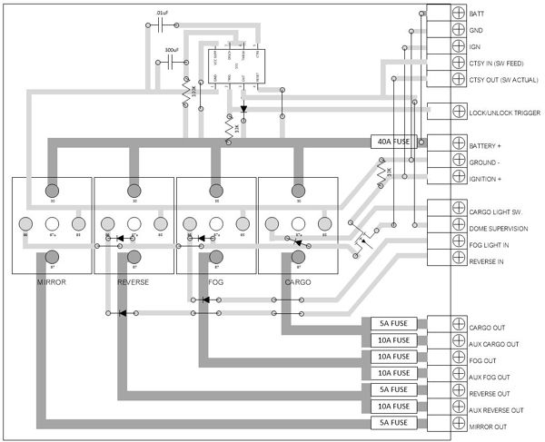
The laser printer method is definitely the way i'm going (hence this picture - it's the reversed version I'll need.).
Looking to find a kit that has everything i need, with chemicals and bits would be nice - i dont think i have any bits that tiny....
eBay has some companies that accept gerber pcb drawings to manufacture really nice green filmed, white printed, drilled boards - but i cant generate gerber files, and the free version sucks.
Looking to find a kit that has everything i need, with chemicals and bits would be nice - i dont think i have any bits that tiny....
eBay has some companies that accept gerber pcb drawings to manufacture really nice green filmed, white printed, drilled boards - but i cant generate gerber files, and the free version sucks.
Cargo Master
Joined: Jan 2012
Posts: 3,053
Likes: 21
From: Pittsburgh, PA
The laser printer method is definitely the way i'm going (hence this picture - it's the reversed version I'll need.).
Looking to find a kit that has everything i need, with chemicals and bits would be nice - i dont think i have any bits that tiny....
eBay has some companies that accept gerber pcb drawings to manufacture really nice green filmed, white printed, drilled boards - but i cant generate gerber files, and the free version sucks.
Looking to find a kit that has everything i need, with chemicals and bits would be nice - i dont think i have any bits that tiny....
eBay has some companies that accept gerber pcb drawings to manufacture really nice green filmed, white printed, drilled boards - but i cant generate gerber files, and the free version sucks.
Believe it or not, radio shack use to have a lot of the stuff. I went to the local on in college and they had two bottle of ferric chloride on the shelf.
Never looked into buying a kit, but I can get you the drill bit sizes tonight if that will help.
Thread Starter
|
Elder User
Joined: Mar 2013
Posts: 844
Likes: 0
From: Dirty Water
Ya, I've been going to eBay, Radio Shack, and You-Do-It in Needham. You-Do-It had big bottles, I just need a small one.
I still need to get an exact list of what I need as far as chemicals, and how much is required for a board that big... i don't see myself needing leftovers any time soon.
I still need to get an exact list of what I need as far as chemicals, and how much is required for a board that big... i don't see myself needing leftovers any time soon.
FTE Stories
Ford Trucks for Ford Truck Enthusiasts

Top 10 Fords at 2026 Carlisle Ford Nationals
Joe Kucinski
3 Best / 3 Worst Parts of Modern Ford Ownership
Brett Foote
10 Amazing Upgrades That Solve Common Ford Truck Owner Headaches
Pouria Savadkouei
Every 2026 Ford Engine Explained
Brett Foote
10 Ugly Ford Trucks That We Still Kinda Love
Joe Kucinski
10 Things Every Truck Owner NEEDS (2026 Edition)
Michael S. Palmer
Rezvani's Latest Post-Apocalyptic Monster Is a Ford F-150 Raptor Underneath
Verdad Gallardo
Top 10 Most Expensive Ford Trucks Ever Sold on Bring a Trailer
Joe Kucinski
2027 Ford Super Duty Buyer's Guide (Every Model, Engine, & Package)
Brett Foote
Cargo Master
Joined: Jan 2012
Posts: 3,053
Likes: 21
From: Pittsburgh, PA
I used a 32 oz bottle when I did it. That gave me enough to immerse the board in it. It was also the only bottle available.... But anyway, when you are done you either throw it out or just pour it back into the bottle. Its not a one time use liquid. You can use for a good while until it becomes enriched with copper.
One other thing I thought of. How wide are the skinniest traces? You may want to increase the line size by a few mils to keep it safe. I want to say that 10 or 15 mil was the minimum width my professor said we were capable of doing by hand. Anything skinnier needed to be left to the machines.
One other thing I thought of. How wide are the skinniest traces? You may want to increase the line size by a few mils to keep it safe. I want to say that 10 or 15 mil was the minimum width my professor said we were capable of doing by hand. Anything skinnier needed to be left to the machines.
Thread Starter
|
Elder User
Joined: Mar 2013
Posts: 844
Likes: 0
From: Dirty Water
2 1/4 points (line size in MS Visio) = 31.25 mils, according to the Google machine. Seems like I'm safe. That board pictured is just under 5 1/2" x 4".
I didn't do any formal calculating or engineering about the larger traces - how thick the board copper is vs. how much of a load can pass through them at what widths. I'm sure there's a calculation or something. They are currently a perfect 125 mils, and will be fused at 10 amps, though i may end up needing different fuses. the bottom is a fuse block, for cargo, aux cargo, fog, aux fog, reverse, aux reverse, and mirror lights. Some will be relatively low load, as the factory relays are still in place, but some will directly carry a load.
EDIT: I just checked online, and it seems my traces are plenty wide enough. It would stink to fry one when the lights go on. Also thinking about making the relays plug-in instead of soldered. (I already have PCB mount relays).
I also haven't figured out how to do the connectors on the outside. Having done numerous remote starters, I want it to basically be wired the exact same way, with one big heavy connector for the higher load leads, and a couple smaller ones for the smaller leads. The top left of the picture is of the two separate boards, and between them could be a premade 6 or 8' lead, exactly like the one that goes from a remote starter brain to it's antenna module It'd be nice to get one of those jumpers premade, and get the ends to PCB mount. Looking on eBay now, and will check locally later.
I didn't do any formal calculating or engineering about the larger traces - how thick the board copper is vs. how much of a load can pass through them at what widths. I'm sure there's a calculation or something. They are currently a perfect 125 mils, and will be fused at 10 amps, though i may end up needing different fuses. the bottom is a fuse block, for cargo, aux cargo, fog, aux fog, reverse, aux reverse, and mirror lights. Some will be relatively low load, as the factory relays are still in place, but some will directly carry a load.
EDIT: I just checked online, and it seems my traces are plenty wide enough. It would stink to fry one when the lights go on. Also thinking about making the relays plug-in instead of soldered. (I already have PCB mount relays).
I also haven't figured out how to do the connectors on the outside. Having done numerous remote starters, I want it to basically be wired the exact same way, with one big heavy connector for the higher load leads, and a couple smaller ones for the smaller leads. The top left of the picture is of the two separate boards, and between them could be a premade 6 or 8' lead, exactly like the one that goes from a remote starter brain to it's antenna module It'd be nice to get one of those jumpers premade, and get the ends to PCB mount. Looking on eBay now, and will check locally later.
Cargo Master
Joined: Jan 2012
Posts: 3,053
Likes: 21
From: Pittsburgh, PA
I was off on my number then lol. I don't know where I got 10 to 15 lol.
This should help you make sure your traces can meet the 10 amp requirement. It's fairly simple.
http://www.ultracad.com/articles/fusing.pdf
This should help you make sure your traces can meet the 10 amp requirement. It's fairly simple.
http://www.ultracad.com/articles/fusing.pdf
Thread Starter
|
Elder User
Joined: Mar 2013
Posts: 844
Likes: 0
From: Dirty Water
I was off on my number then lol. I don't know where I got 10 to 15 lol.
This should help you make sure your traces can meet the 10 amp requirement. It's fairly simple.
http://www.ultracad.com/articles/fusing.pdf
This should help you make sure your traces can meet the 10 amp requirement. It's fairly simple.
http://www.ultracad.com/articles/fusing.pdf
I was just looking here:
The CircuitCalculator.com Blog » PCB Trace Width Calculator
I can't find online how thick the Radio Shack board's copper is though.


Cargo Master
Joined: Jan 2012
Posts: 3,053
Likes: 21
From: Pittsburgh, PA
Digikey may be able to get you closer to a thickness. They will at least tell how much copper was used on a given board dimension which would let you calculate it. But that is getting really in depth...
Invalid Request
Invalid Request
Thread Starter
|
Elder User
Joined: Mar 2013
Posts: 844
Likes: 0
From: Dirty Water
Digikey may be able to get you closer to a thickness. They will at least tell how much copper was used on a given board dimension which would let you calculate it. But that is getting really in depth...
Invalid Request
Invalid Request
Another good reason these things are good to talk out with someone else, thanks for all the input.