


thekingofcows Build Thread
Post Fiend
Joined: Nov 2009
Posts: 7,669
Likes: 2
I dont think you'll have a flange on flange problem. Im thinking you'll have an issue with the round splined portion slipping inside the round hole (albeit smaller diameter and more of a press fit - nice thinking on that trick too) even after welded. Do you see what Im saying? I wonder if something like a half moon key or a flat bar type key would work? Just suggestions and thinking out loud.
Thread Starter
|
Elder User
Joined: Oct 2009
Posts: 871
Likes: 1
From: New Albany, MS
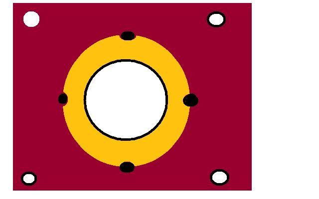
Based upon my world class drawing you should be able to easily tell how the yoke will work. The yellow is the round splined part the purple is the flange. The yellow will be welded to the flange and i will drill some 1/8 inch holes similar to the depiction above where the black dots are to help detour twistage.
Thread Starter
|
Elder User
Joined: Oct 2009
Posts: 871
Likes: 1
From: New Albany, MS
Done
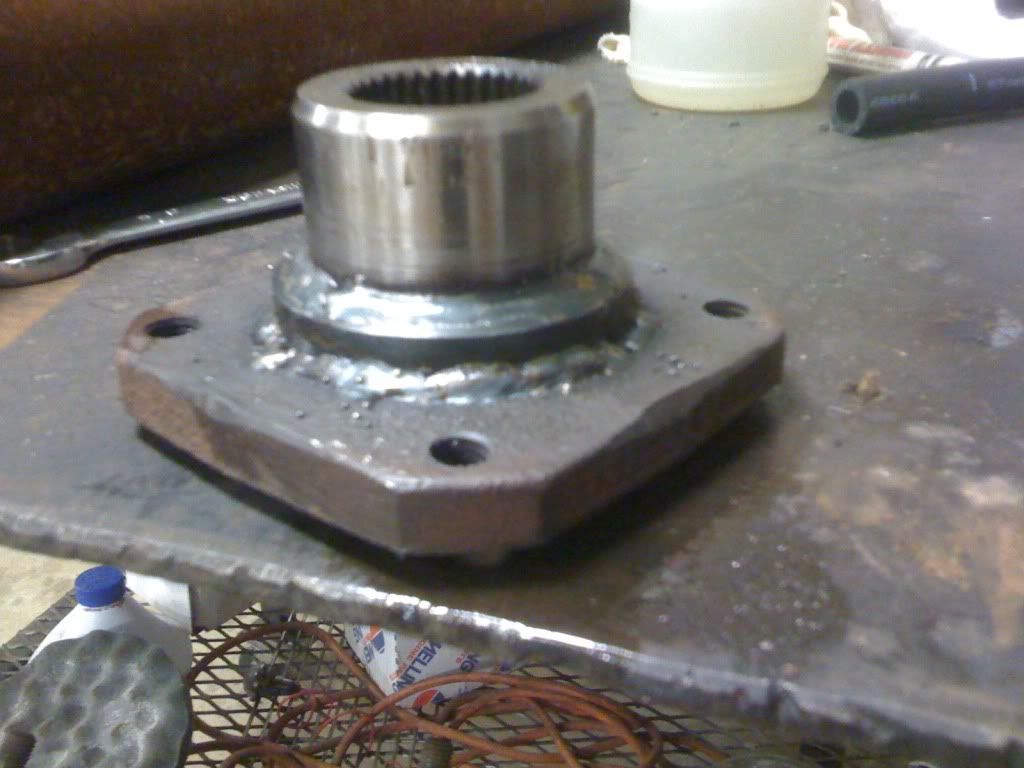
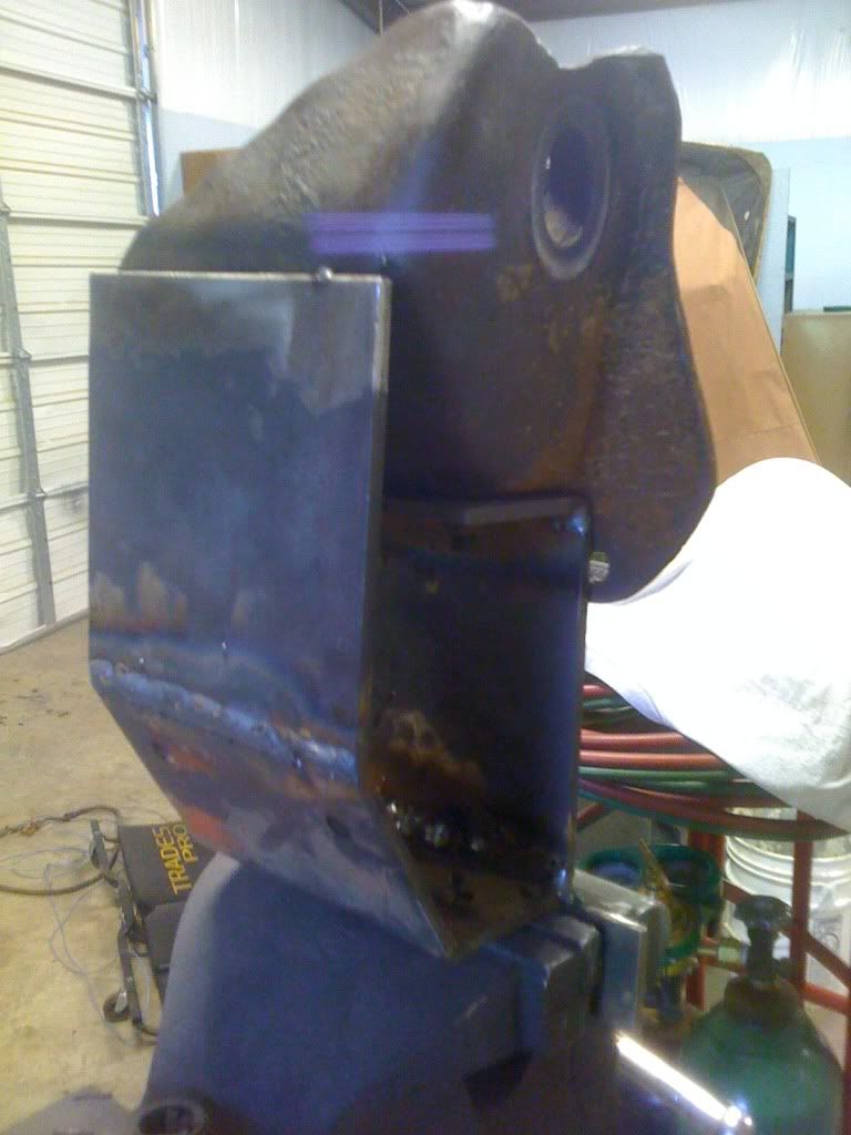
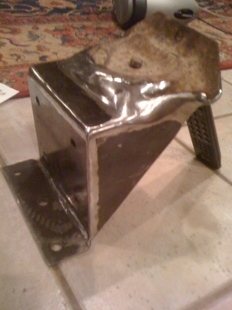
I managed to save the original flange by turning a bushing down and boring the hole in the flange bigger... I pleased with the way it turned out considering the hick-up I had with the non concentric holes.
Below you can see how I "stepped" up the strength by drilling holes and driving in roll pins.
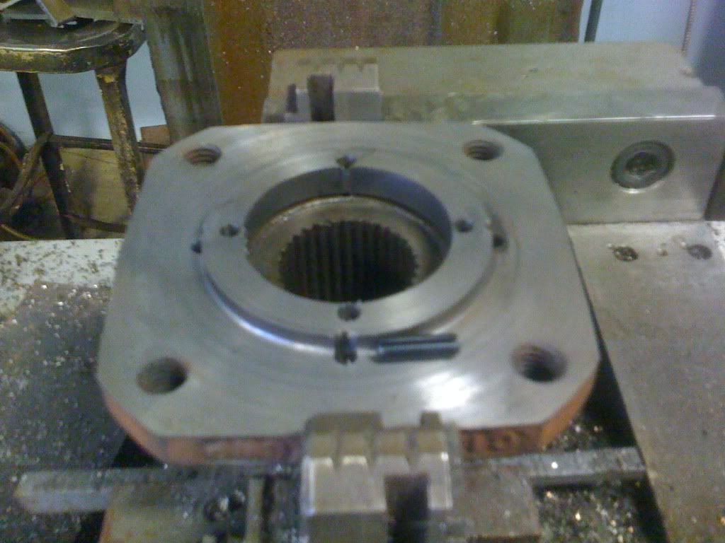
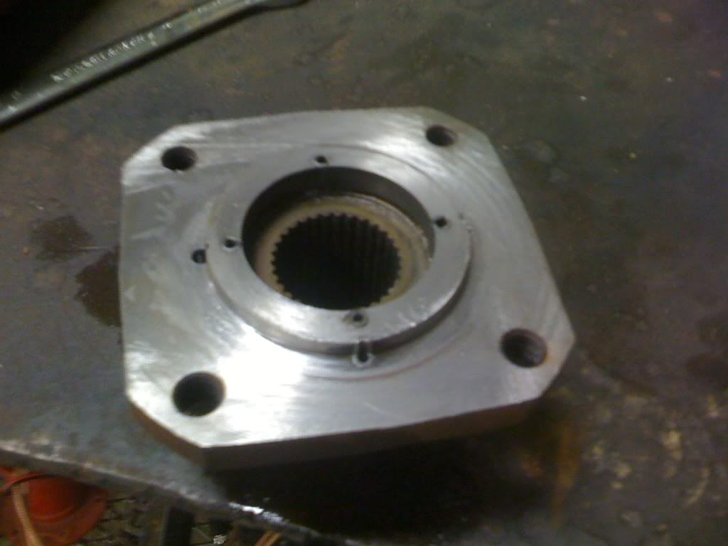
I managed to save the original flange by turning a bushing down and boring the hole in the flange bigger... I pleased with the way it turned out considering the hick-up I had with the non concentric holes.
Below you can see how I "stepped" up the strength by drilling holes and driving in roll pins.
Thread Starter
|
Elder User
Joined: Oct 2009
Posts: 871
Likes: 1
From: New Albany, MS
I figured I'd post an update sense it seems like it has been forever since I posted something here, so I figured give ya'll an update.
I relocated My pickup from my friend's shop to mine.
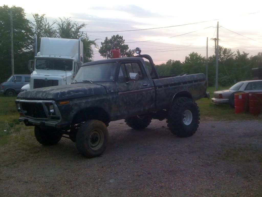
Beautiful Sight Huh?
I secured the axle (very very loosely) under the front just enough so that I could winch the truck up on a trailer.
Once I got it to my shop. I lifted the front end via a friends awesome air jack. Once I lifted the front I bolted the 44z on to see what type of front suspension modifications were going to be necessarry.
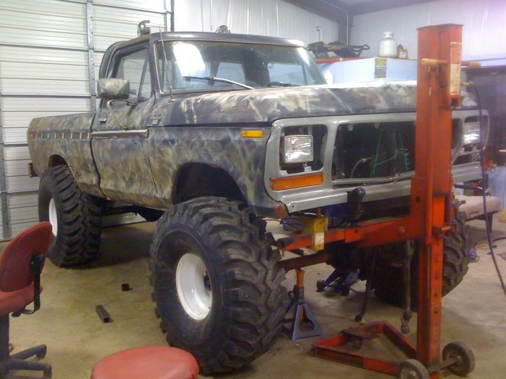
Looks 'alright' like that, two bad there is nothing alright about it in the picture. It still lacked a stable front suspension, steering, brake lines a trac bar, driveshafts and Im sure some other nuts and bolts Im forgetting.
Currently I have been working on my front suspension. I of course already showed ya'll the coil buckets I made. To achieve the rest of the lift I bought a set of 6 inch superlift coil springs. (On a side note, I can't believe how little these springs actually squish, Im hoping they will soften up a bit with a heavy bumper a winch and a bunch of suspension cycles.) For my radius arms I bought some c wedges from the graveyard, and for the other end we built some 6 inch drop brackets to secure the axle.
I never snapped a pick of the completed brackets, but I am sure many of you are very familiar with these.
This is not the set up I probably want to run forever, but for right now I want to get this truck rolling so this proved to be the cheapest and quickest route.
Now I need to find a source on brake lines for the front of an 80's 3\4 chebby so I can plumb my brakes
Also I want to build an adjustable trac bar, can any one provide any tricks to that?
Finally I found the steering assembly for a peterbilt truck for free recently, I there is someone who knows the advantages and disadvatages for running an eighteen wheeler's tie rods or if its even possible feel free to chime in.
Thanks for mostly good insight so far.
I relocated My pickup from my friend's shop to mine.
Beautiful Sight Huh?
I secured the axle (very very loosely) under the front just enough so that I could winch the truck up on a trailer.
Once I got it to my shop. I lifted the front end via a friends awesome air jack. Once I lifted the front I bolted the 44z on to see what type of front suspension modifications were going to be necessarry.
Looks 'alright' like that, two bad there is nothing alright about it in the picture. It still lacked a stable front suspension, steering, brake lines a trac bar, driveshafts and Im sure some other nuts and bolts Im forgetting.
Currently I have been working on my front suspension. I of course already showed ya'll the coil buckets I made. To achieve the rest of the lift I bought a set of 6 inch superlift coil springs. (On a side note, I can't believe how little these springs actually squish, Im hoping they will soften up a bit with a heavy bumper a winch and a bunch of suspension cycles.) For my radius arms I bought some c wedges from the graveyard, and for the other end we built some 6 inch drop brackets to secure the axle.
I never snapped a pick of the completed brackets, but I am sure many of you are very familiar with these.
This is not the set up I probably want to run forever, but for right now I want to get this truck rolling so this proved to be the cheapest and quickest route.
Now I need to find a source on brake lines for the front of an 80's 3\4 chebby so I can plumb my brakes
Also I want to build an adjustable trac bar, can any one provide any tricks to that?
Finally I found the steering assembly for a peterbilt truck for free recently, I there is someone who knows the advantages and disadvatages for running an eighteen wheeler's tie rods or if its even possible feel free to chime in.
Thanks for mostly good insight so far.
FTE Stories
Ford Trucks for Ford Truck Enthusiasts

Top 10 Fords at 2026 Carlisle Ford Nationals
Joe Kucinski
3 Best / 3 Worst Parts of Modern Ford Ownership
Brett Foote
10 Amazing Upgrades That Solve Common Ford Truck Owner Headaches
Pouria Savadkouei
Every 2026 Ford Engine Explained
Brett Foote
10 Ugly Ford Trucks That We Still Kinda Love
Joe Kucinski
10 Things Every Truck Owner NEEDS (2026 Edition)
Michael S. Palmer
Rezvani's Latest Post-Apocalyptic Monster Is a Ford F-150 Raptor Underneath
Verdad Gallardo
Top 10 Most Expensive Ford Trucks Ever Sold on Bring a Trailer
Joe Kucinski
2027 Ford Super Duty Buyer's Guide (Every Model, Engine, & Package)
Brett Foote


Posting Guru
Joined: Jun 2009
Posts: 1,174
Likes: 0
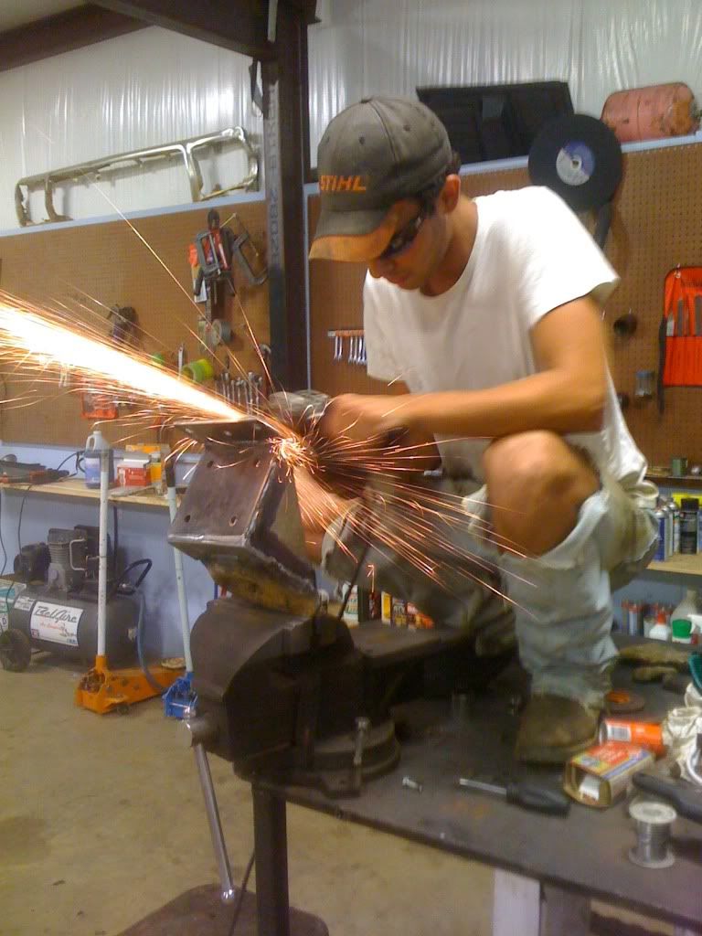
Pants=Although they remind me a bit too much of Jon Bon Jovi in the 80's, I may have been known to own a few pairs like that. It takes a true man to shower sparks on his own bare knees....

Thread Starter
|
Elder User
Joined: Oct 2009
Posts: 871
Likes: 1
From: New Albany, MS
I believe I have figured out the way I am going to accomplish everything... Mostly at least.
I plan on building my trac bar and steering links out of 1 1/4 x .25 DOM tubing, and for the steering components i'll use chevy one ton tie rod ends. Which presents a question:
If I wanted to have my steering on top of the steering arm instead of under it, could I ream the tie rod hole out with appropiate reamer to allow the bigger chevy joints to attach at the top?
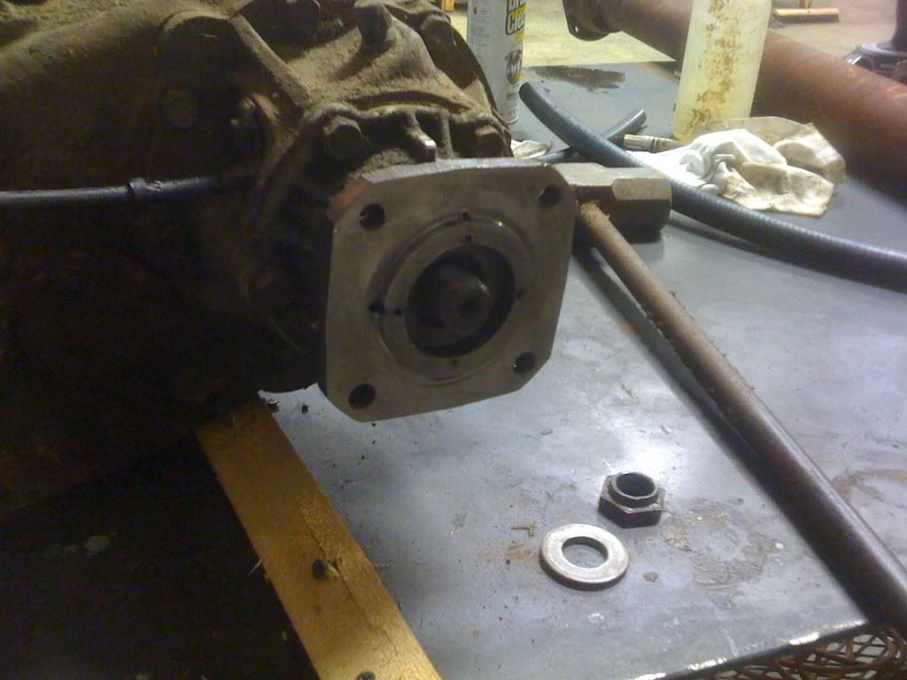
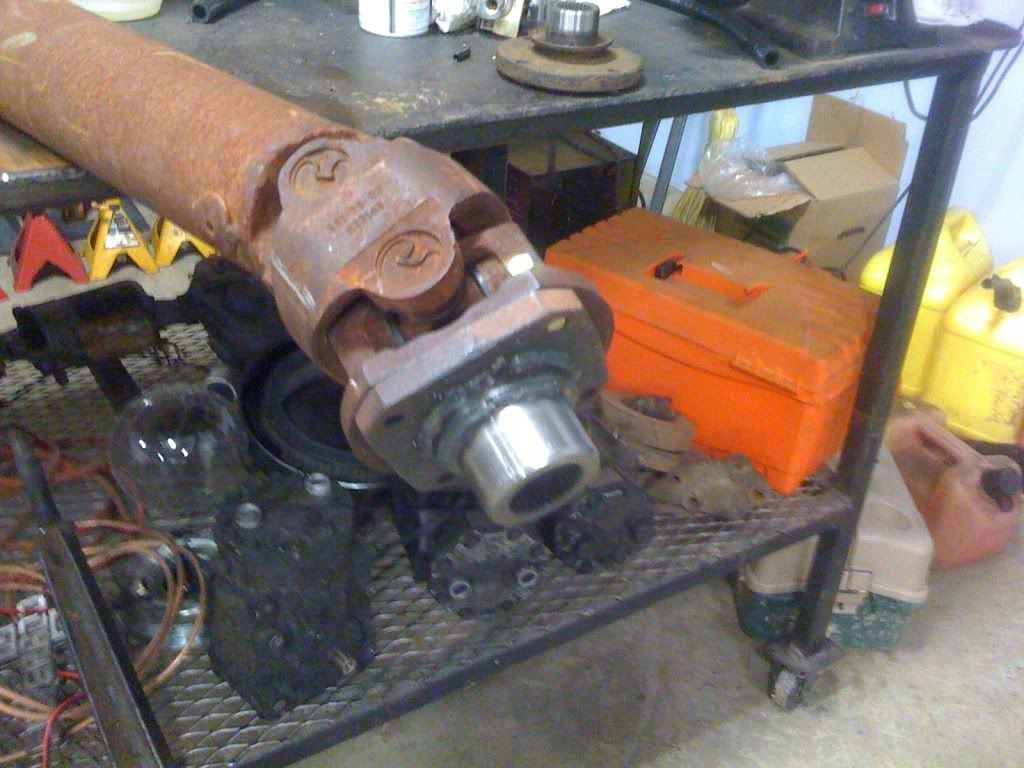
Second question, A friend of mine happened upon this the other day and gave it to me for free.
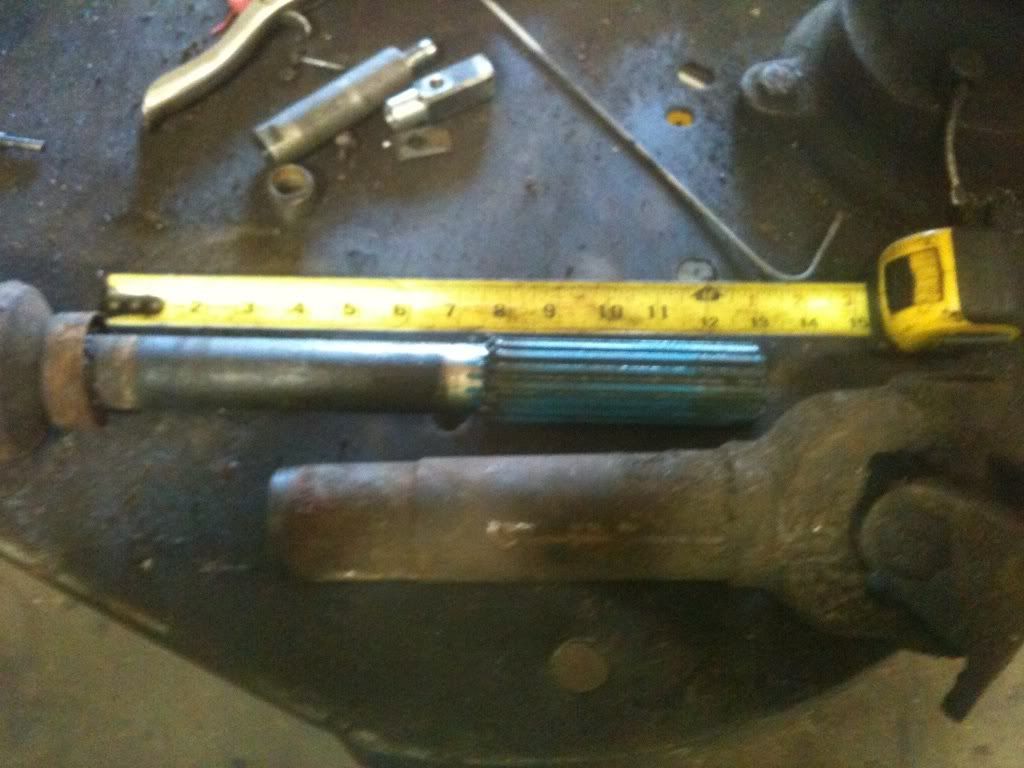
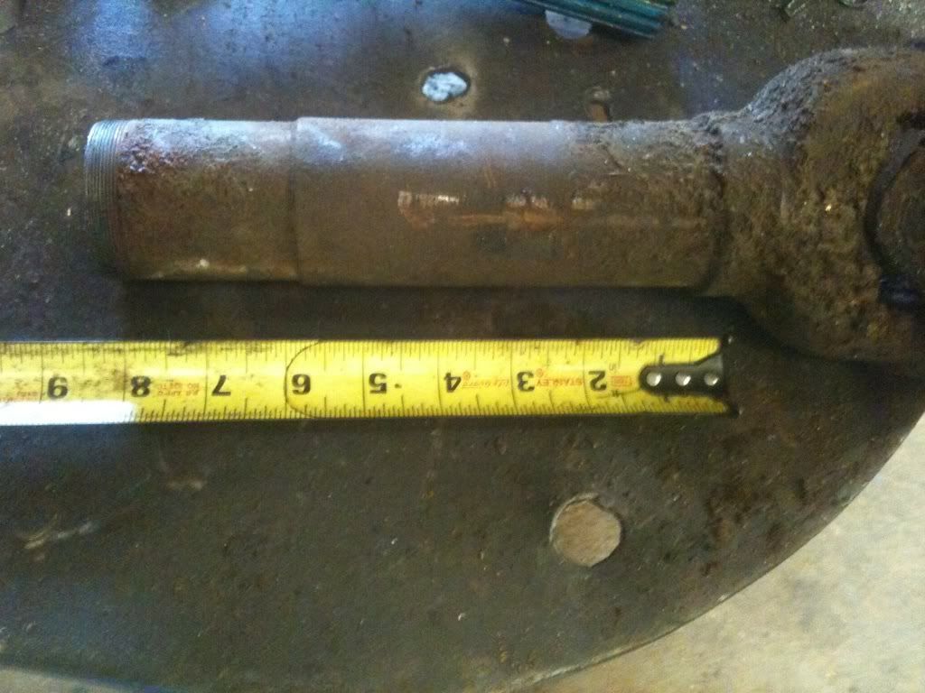
That's right thats a long travel spicer slip yoke. Thats a pretty cool find huh, it even still has the blue stuff on the splines, and on top of that it has a 1410 u joint! So this is what i'd like to run a my rear driveshaft i think. But the only problem is that the driveshaft tubes that I have don't match. The cardan joint driveshaft is 3.5 inches and the long slip yoke looks like it goes on a 2.5 or 3 inch tube.
So my question is, can I turn a bushing down to make the slipyoke fit, or will that weaken the shaft? And if a bushing would work, could simply use cold rolled round steel.
Thanks for ya'lls input. -thekingofcows-
I plan on building my trac bar and steering links out of 1 1/4 x .25 DOM tubing, and for the steering components i'll use chevy one ton tie rod ends. Which presents a question:
If I wanted to have my steering on top of the steering arm instead of under it, could I ream the tie rod hole out with appropiate reamer to allow the bigger chevy joints to attach at the top?
Second question, A friend of mine happened upon this the other day and gave it to me for free.
That's right thats a long travel spicer slip yoke. Thats a pretty cool find huh, it even still has the blue stuff on the splines, and on top of that it has a 1410 u joint! So this is what i'd like to run a my rear driveshaft i think. But the only problem is that the driveshaft tubes that I have don't match. The cardan joint driveshaft is 3.5 inches and the long slip yoke looks like it goes on a 2.5 or 3 inch tube.
So my question is, can I turn a bushing down to make the slipyoke fit, or will that weaken the shaft? And if a bushing would work, could simply use cold rolled round steel.
Thanks for ya'lls input. -thekingofcows-
Post Fiend
Joined: Nov 2009
Posts: 7,669
Likes: 2
yeah, just ream the top of the knuckle. You need an 8* reamer if memory serves. I assume you'll be threading the ID of the DOM rather than weld in bungs? The shank on the Chebby TREs is 7/8" and the ID of the DOM will be 3/4"
I dont understand what you mean when you say you want to make a bushing to make the driveshaft fit.
I dont understand what you mean when you say you want to make a bushing to make the driveshaft fit.
Thread Starter
|
Elder User
Joined: Oct 2009
Posts: 871
Likes: 1
From: New Albany, MS
Im connecting a weld yoke that is for roughly 2.5 inch (the long slip yoke) tube to a 3.5 inch driveshaft tube that my 1350 cv is designed for. Seems like I couldturn a bushing down to allow my 3.5 tube to accept a 2.5 inch yoke
Thread Starter
|
Elder User
Joined: Oct 2009
Posts: 871
Likes: 1
From: New Albany, MS
Ok This most likely will be a dumb question but here it goes.
I want to make my own adjustable drag link. And my plans where to make it out of the same size dom that I make my steering components out of, and utilize heim joints. However i noticed by looking at the commericially available ones they don't use heims and don't seem to be all that special. So my question simply is:
I could in theory machine something like this
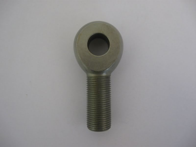
And I would machine it to accept the stock 'poly' bushings.
So is this a dumb idea or would it work?
Also for any of you mettalurgy experts out there, could I build these links out of cold rold round? Or would that not suffice?
I know its a lot of random questions but I really do appreciate ya'lls input ...most of the time..
I want to make my own adjustable drag link. And my plans where to make it out of the same size dom that I make my steering components out of, and utilize heim joints. However i noticed by looking at the commericially available ones they don't use heims and don't seem to be all that special. So my question simply is:
I could in theory machine something like this
And I would machine it to accept the stock 'poly' bushings.
So is this a dumb idea or would it work?
Also for any of you mettalurgy experts out there, could I build these links out of cold rold round? Or would that not suffice?
I know its a lot of random questions but I really do appreciate ya'lls input ...most of the time..