


thekingofcows Build Thread
Thread Starter
|
Elder User
Joined: Oct 2009
Posts: 871
Likes: 1
From: New Albany, MS
Ha, thanks for your concern, but that isn't me in the picture, he is a friend helping me out on the project. He has a CJ7 and a chebby I help him on. Also, he has a woodworking shop, so between my metal shop and his woodworking shop we can accomplish a few things.
Postmaster
Joined: Aug 2008
Posts: 4,092
Likes: 0
From: Olympia
Hahah. Well I hope you guys arn't planning to make anything for your truck in woodshop.
Then again... with wooden lift blocks it would be like adjustable ride!
Get it wet and it'll swell up and lift the truck, when it dries out it'll go back down..
Then when they crack and fall out you'll have a low rider!!

Then again... with wooden lift blocks it would be like adjustable ride!
Get it wet and it'll swell up and lift the truck, when it dries out it'll go back down..
Then when they crack and fall out you'll have a low rider!!

Post Fiend
Joined: Oct 2003
Posts: 6,949
Likes: 1
From: utica il
hey, i've seen some pretty badass custom interiors made with hard woods that were stained and hand carved. if you use it sparingly, it looks cool. too much and it looks like your interior was made by a lonely old man who sits on the porch widdling wood all day.
Thread Starter
|
Elder User
Joined: Oct 2009
Posts: 871
Likes: 1
From: New Albany, MS
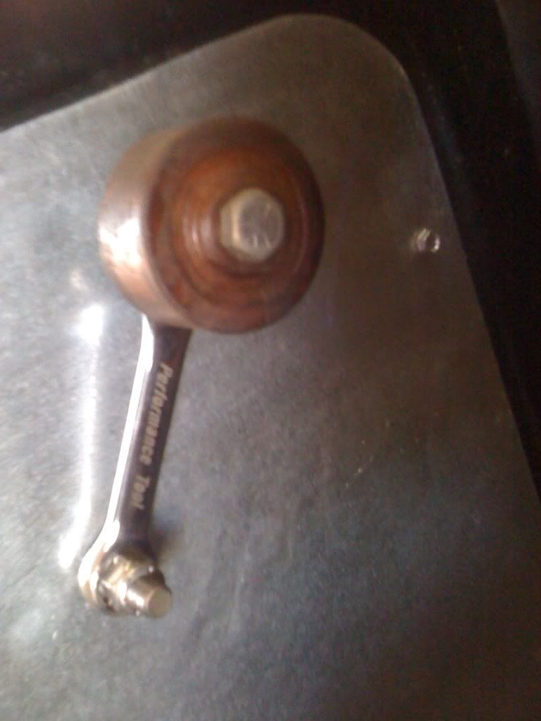
My interior is pretty subtle, but it actually has some wooden pieces, the window crank for example had stripped out splines, so I cut off the shaft and welded a piece of 3/8 x 16 rod to it. Then I took a stubby import wrench and welded a nut to either end then my friend made some simple handles out of walnut, and glued a sleeve in the middle the rest should be self explanatory.
Postmaster
Joined: Aug 2008
Posts: 4,092
Likes: 0
From: Olympia
FTE Stories
Ford Trucks for Ford Truck Enthusiasts

Top 10 Fords at 2026 Carlisle Ford Nationals
Joe Kucinski
3 Best / 3 Worst Parts of Modern Ford Ownership
Brett Foote
10 Amazing Upgrades That Solve Common Ford Truck Owner Headaches
Pouria Savadkouei
Every 2026 Ford Engine Explained
Brett Foote
10 Ugly Ford Trucks That We Still Kinda Love
Joe Kucinski
10 Things Every Truck Owner NEEDS (2026 Edition)
Michael S. Palmer
Rezvani's Latest Post-Apocalyptic Monster Is a Ford F-150 Raptor Underneath
Verdad Gallardo
Top 10 Most Expensive Ford Trucks Ever Sold on Bring a Trailer
Joe Kucinski
2027 Ford Super Duty Buyer's Guide (Every Model, Engine, & Package)
Brett FooteThread Starter
|
Elder User
Joined: Oct 2009
Posts: 871
Likes: 1
From: New Albany, MS
Well it was out of necessity sorta, and it was cheap, the story is, the splines on my regulator shaft were stripped, the allen head screw in the middle of the window crank was broken off. So thats why I did it the way I did. It provided a bit of contrast to my metal door panel, I made armrests to match, and of course did both sides.
Thread Starter
|
Elder User
Joined: Oct 2009
Posts: 871
Likes: 1
From: New Albany, MS
Got back from my journey to north carolina this weekend and got to put in a little time in my shop sunday.
I do have both coil buckets finished, painted, and installed, but I didn't think to take a picture... so I upload one later. Yesterday I tackled a project that has been on my mind for some time.
Dilemma #1:
I wanted to run a double cardan joint at the rear output of of my T-case, however after checking on the pricing of a new one ton cv encrusted driveshaft I quickly discovered how exepensive it can get.
My Solution:
I bought a late model driveshaft off like an 2004 superduty. It comes equipped with a 1350 cv, and they are all spicer components, so they are all very strong. The best part, it cost only $100. You can't even by some yokes for that, but any way. Here is a picture of the driveshaft.
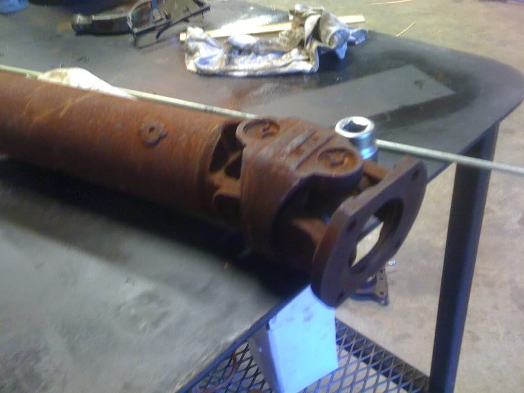
The driveshaft is way longer than it needs to be, so that provides plenty of room for shortening.
Dilemma #2:
If you notice the end of the driveshaft has a flat flange. NP 205's do not.
My Solution:
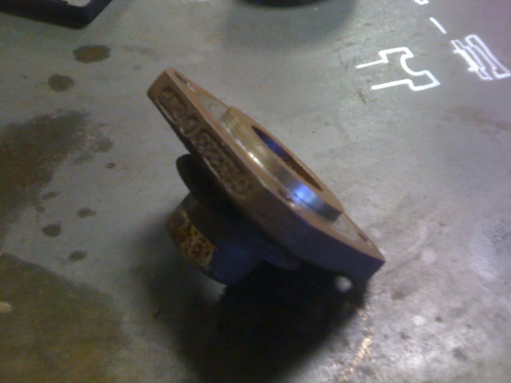
I am combining a flat flange I have, with the original yoke to make my own flange.
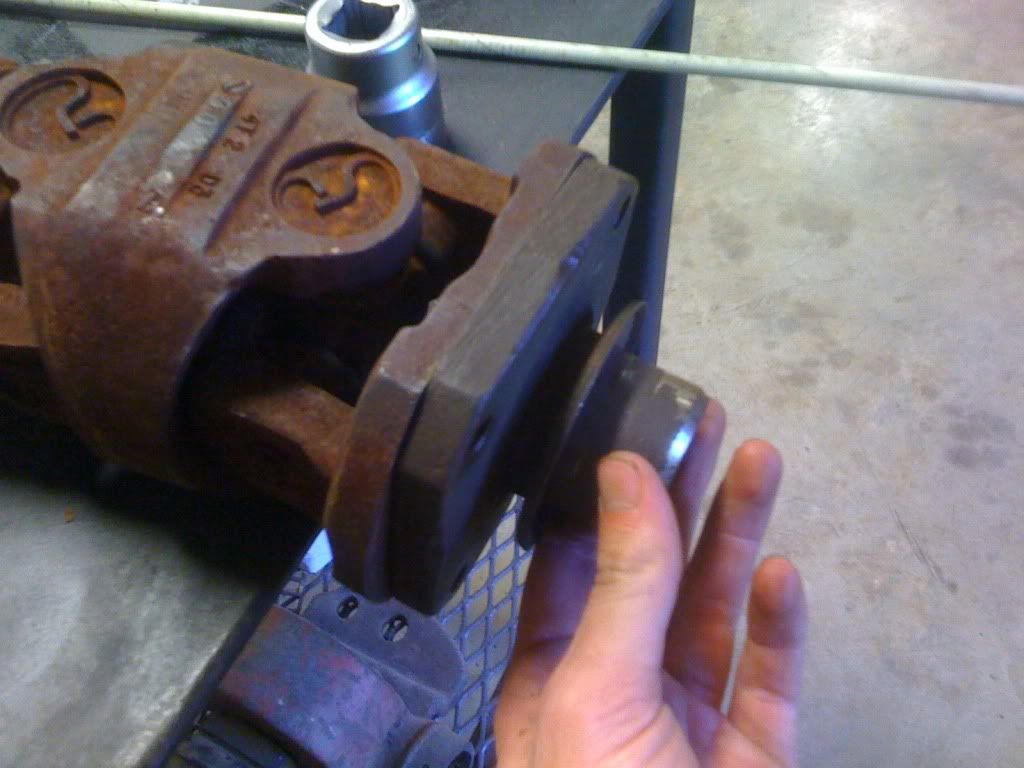
I started with the original 1330 yoke on the transfercase, this yoke provides no good way to connect to the flange on the cv joint. So I sawed off the "ears" of the yoke, and ground them pretty smooth.
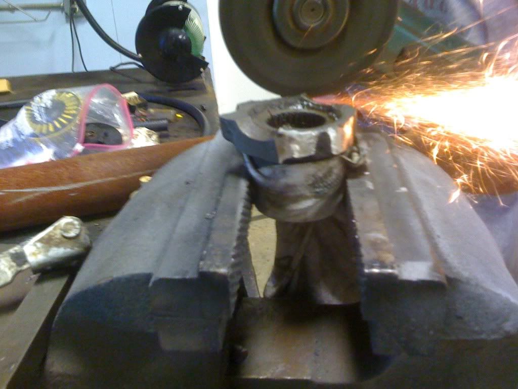
As you can see I ground the yoke roughly round.
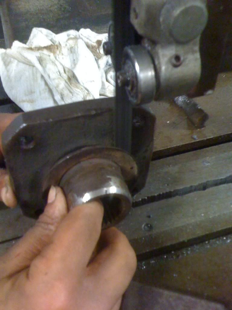
Next I chucked it up in m y 1944 sidney lathe. and faced it flat and turned it to an exact diameter of 2.15.
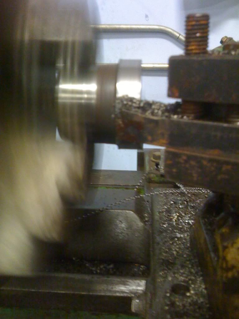
I have some pictures on another camera of the finished perfectly round yoke, but i forgot to bring it home so I'll upload some more pics soon.
The square flange was my next job. I started by chucking it into my lathe to turn a nose down to fit inside the hole on the cv joint flange...
Next I sawed off the end of the splined portion and ground it flat.
I have more pics that i'll have to upload, and I'll wait to then to explain how I did what I did.
Sorry if this is too many details, feel free to comment if you see any problems.
I do have both coil buckets finished, painted, and installed, but I didn't think to take a picture... so I upload one later. Yesterday I tackled a project that has been on my mind for some time.
Dilemma #1:
I wanted to run a double cardan joint at the rear output of of my T-case, however after checking on the pricing of a new one ton cv encrusted driveshaft I quickly discovered how exepensive it can get.
My Solution:
I bought a late model driveshaft off like an 2004 superduty. It comes equipped with a 1350 cv, and they are all spicer components, so they are all very strong. The best part, it cost only $100. You can't even by some yokes for that, but any way. Here is a picture of the driveshaft.
The driveshaft is way longer than it needs to be, so that provides plenty of room for shortening.
Dilemma #2:
If you notice the end of the driveshaft has a flat flange. NP 205's do not.
My Solution:
I am combining a flat flange I have, with the original yoke to make my own flange.
I started with the original 1330 yoke on the transfercase, this yoke provides no good way to connect to the flange on the cv joint. So I sawed off the "ears" of the yoke, and ground them pretty smooth.
As you can see I ground the yoke roughly round.
Next I chucked it up in m y 1944 sidney lathe. and faced it flat and turned it to an exact diameter of 2.15.
I have some pictures on another camera of the finished perfectly round yoke, but i forgot to bring it home so I'll upload some more pics soon.
The square flange was my next job. I started by chucking it into my lathe to turn a nose down to fit inside the hole on the cv joint flange...
Next I sawed off the end of the splined portion and ground it flat.
I have more pics that i'll have to upload, and I'll wait to then to explain how I did what I did.
Sorry if this is too many details, feel free to comment if you see any problems.
Thread Starter
|
Elder User
Joined: Oct 2009
Posts: 871
Likes: 1
From: New Albany, MS
Well I finished most of the yoke. And realized I messed something up...
But first I describe the process. I turned the old yoke to exactly 2.15".
I then bored a matching whole on the plate to 2.147" I threw the bigger one into the freezer and heated up the plate. Once the yoke was freezing cold i took it out and slid it into the corresponding undersized hole.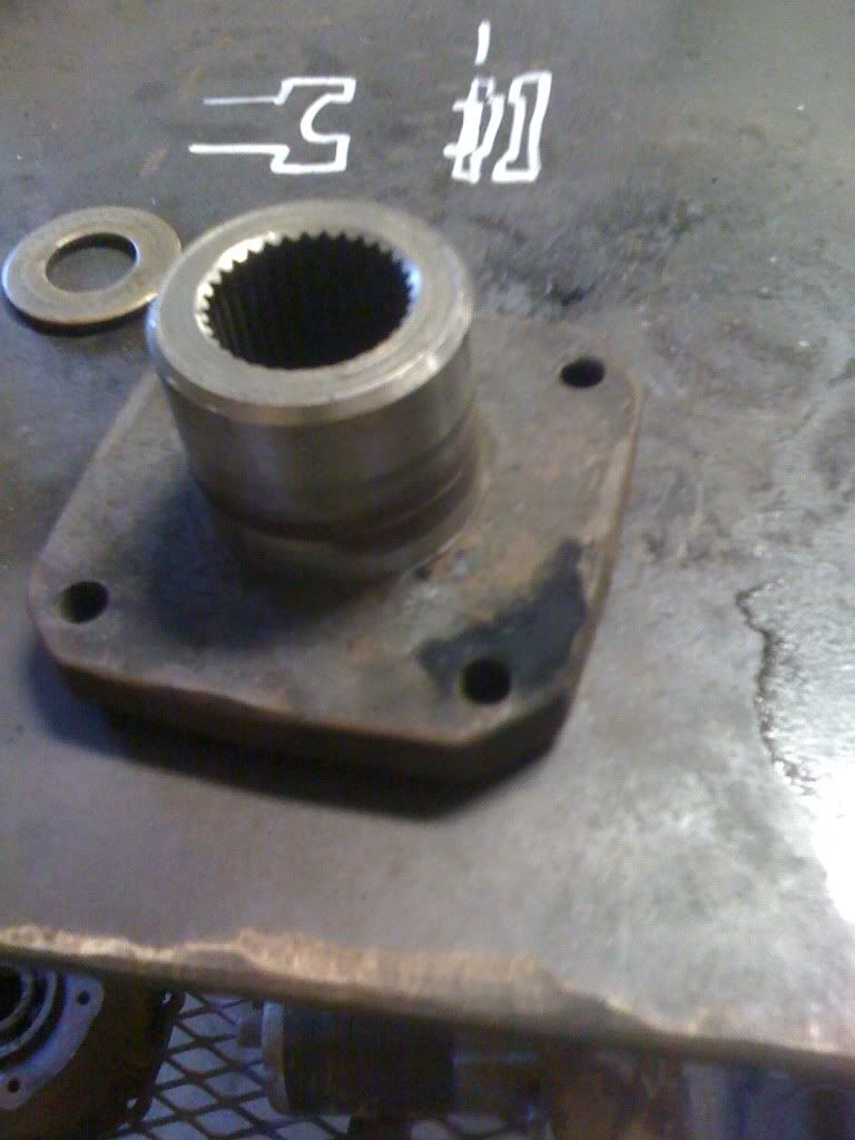
The difference in diameters made for a really tight fit.
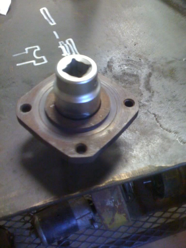
I also bored a hole big enough to fit a socket into so I could take the yoke on and off, a very important consideration.
All this was fine and dandy until I chucked it into my late and checked it concentricity. I was off a noticeable ammount. So I suppose the flat flange is now scrap iron... back to drawing board again i suppose. This time I plan on running as many operations as I possibly can on the lathe to keep my different setups to a minimum.
I am just learning about machining so I suppose i just take it as a good lesson learned...
But first I describe the process. I turned the old yoke to exactly 2.15".
I then bored a matching whole on the plate to 2.147" I threw the bigger one into the freezer and heated up the plate. Once the yoke was freezing cold i took it out and slid it into the corresponding undersized hole.
The difference in diameters made for a really tight fit.
I also bored a hole big enough to fit a socket into so I could take the yoke on and off, a very important consideration.
All this was fine and dandy until I chucked it into my late and checked it concentricity. I was off a noticeable ammount. So I suppose the flat flange is now scrap iron... back to drawing board again i suppose. This time I plan on running as many operations as I possibly can on the lathe to keep my different setups to a minimum.
I am just learning about machining so I suppose i just take it as a good lesson learned...
Post Fiend
Joined: Nov 2009
Posts: 7,669
Likes: 2
uuuuuugh, why not buy a 205 CV flange?
That would get my vote if you do not have a way to balance and keep the splines 100000% true inside the flange. Furthermore, Im not sure if a weld will hold up in shear without out some sort of key type tab to keep the splined portion from spinning inside the flange.
A+ for the effort. The lathe gave me a semi-chub.
Call Jesse at HAD - 530-877-2875 for the flange if you choose to go that route.
on the window regulator do-hickey....
reminds me of how I had to fix my 4wheeler after Paul decided to break it. It also reminds me of the funny story surrounding HOW he broke it.
God bless booze. God bless us every one.
EDIT:
ok so I went back and read this whole thread because honestly I didnt remember it. - I reiterate....cool build. Looks to be on the cheap and self built. Two big bonus points in my book.
ever see the door panels and speaker box I built for George?
Thread Starter
|
Elder User
Joined: Oct 2009
Posts: 871
Likes: 1
From: New Albany, MS
Alpha, good comments. Im not only welding the yoke, but im running in roll pins between the two yokes. That probably doesn't make good sense but when I get there, I'll take pictures and explain. Im doing it this way because I already have both yokes. And that is cheaper than buying one.