


The engine that failed

More Turbo


Joined: Nov 2015
Posts: 715
Likes: 112
Thanks for the pictures.
We have some work to do if it is OK with you.
You may have done this but let me check anyway.
In order to check to see if the timing Tab and piston TDC is the same you need two points of reference and the midway point between.
Bring the piston to TDC and set the dial indicator to zero only this time put the dial indicator in the center of the piston so piston rock doesn't effect the reading.
Turn the crank Counter Clockwise till the dial goes past .050" then stop and turn the crank Clockwise till the indicator reads .040"
The timing should be 10* BTDC
Now turn the crank Clockwise past TDC till the dial reads .050" in the other direction and stop.
Turn the crank Counter Clockwise till the dial reads .040" and stop.
The timing should be 10* ATDC. You will have to eyeball the distance since the timing tab stops at 6* ATDC.
The TDC mark needs to halfway between the two .040" points. (The .040" points may be slightly different than 10*)
Next is cam timing.
First off the 3 way gear changes the cam timing by 4* crank angle for each position, not 2*
Second there is no way of knowing where the cam timing really is unless you check the cam lobe position against the crank position using a degree wheel on the crankshaft.
This is why you get a cam card with all the points of reference.
We also use the degree wheel to verify the actual cam lobe specs in the process.
I can't tell you how many times the cam timing was off with the timing gear set in the correct position.
We are going to take a shortcut for now.
Turn the crank Clockwise till the intake lifter for Cylinder #1 is down.
Place a pushrod into the intake lifter of cylinder #1 and place the dial indicator on the other end of the pushrod making sure it is in line with the pushrod.
Zero the dial. Then turn the crank Clockwise till the intake lifter just begins to rise and slowly continue till the dial reads .050" and stop.
Now look at the timing mark on the harmonic balancer and post the reading here. It should 2* BTDC if the cam is set correctly. The cam card should show this point.
Moderator


Joined: Dec 2007
Posts: 7,987
Likes: 104
From: Boise, Idaho

I used the marks on the timing cover since they're considerably easier to read, and you can see them at the same time as your hand is on the distributor.
On my new engine, the harmonic balancer didn't have the timing mark for it, so I added it. Then, I rotated the balancer until the mark was at 10� and marked it again. Repeat, repeat until i had marks up to 60�. I wouldn't have it any other way, as it's great for timing the whole curve, instead of just base timing.
For priming the oil pump, I went to Harbor Freight and got and 8mm hex drive for my 1/4" drive adapter for my drill .
Then, once oil was in it, I put the bit in and spun it until I had pressure on the gauge on the dash.
Worked slick!
If those drill attachments don't make sense, lemme know.
Thread Starter
|
Lead Driver
Joined: Mar 2008
Posts: 7,190
Likes: 384
From: Near Los Angeles
Thanks to Pmuller and AbandonedBronco. You've both been a great help. I appreciate it.
Pmuller: I will print your instructions and run through them tomorrow. Thanks for taking the time to do a quality control check, so to speak.
Pmuller: I will print your instructions and run through them tomorrow. Thanks for taking the time to do a quality control check, so to speak.
Thread Starter
|
Lead Driver
Joined: Mar 2008
Posts: 7,190
Likes: 384
From: Near Los Angeles
Well, I followed your instructions, Pmuller, and it came out right as it should have. If you look close you can see it is right at 2* btdc.And that was with putting the dial indicator on the p.rod, as you said. The other readings came out as you said too.

With the head gasket, I'm hoping that the side with the blue lines is up??

With the head gasket, I'm hoping that the side with the blue lines is up??
Moderator
Joined: Dec 2007
Posts: 7,987
Likes: 104
From: Boise, Idaho
I believe we have the same head gasket.
Here's mine, installed with the ARP studs.
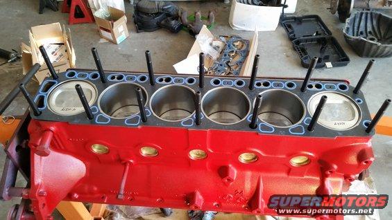
There's the push rod holes on the driver's side and two large water holes on the back of the block to line it up with.
Here's mine, installed with the ARP studs.
There's the push rod holes on the driver's side and two large water holes on the back of the block to line it up with.
Thread Starter
|
Lead Driver
Joined: Mar 2008
Posts: 7,190
Likes: 384
From: Near Los Angeles
I'm happy to know that all is kosher with the cam timing, and that I have the head gasket on correctly. Thanks for the help.
I had to move some things out of the garage to make room. Luckily I covered it with plastic in time. It really poured today. I'm looking for a dry day to set the engine back on its perches.

I wrapped the headers today, and had to cut the alternator bracket more than I was comfortable with to get the front header to line up. I think I'll have to weld a brace/tab on the bracket for strength. I was quickly able to see that the Y pipe I bought would not fit on to the collectors without a bit of help.
I torqued the head @ 80 with the ARP studs. I noticed that the second pass with the t.wrench, just to check, a few of the nuts turned a bit more before the t.wrench clicked again. That surprised me. I thought all them, having been torqued to spec once, would click right away. Oh well.
Working with the header wrap was not fun. Wear long sleeves and a respirator. I bought harbor freight stainless zip ties for the work. But they make me worry, and I'll have to buy some quality ones that won't surrender easily.

My clifford v.cover hits two of the ARP head studs/nuts. I'm forced to use two v.cover gaskets ... with a high rise v.cover... who would have thought?
I had to move some things out of the garage to make room. Luckily I covered it with plastic in time. It really poured today. I'm looking for a dry day to set the engine back on its perches.
I wrapped the headers today, and had to cut the alternator bracket more than I was comfortable with to get the front header to line up. I think I'll have to weld a brace/tab on the bracket for strength. I was quickly able to see that the Y pipe I bought would not fit on to the collectors without a bit of help.
I torqued the head @ 80 with the ARP studs. I noticed that the second pass with the t.wrench, just to check, a few of the nuts turned a bit more before the t.wrench clicked again. That surprised me. I thought all them, having been torqued to spec once, would click right away. Oh well.
Working with the header wrap was not fun. Wear long sleeves and a respirator. I bought harbor freight stainless zip ties for the work. But they make me worry, and I'll have to buy some quality ones that won't surrender easily.
My clifford v.cover hits two of the ARP head studs/nuts. I'm forced to use two v.cover gaskets ... with a high rise v.cover... who would have thought?
Thread Starter
|
Lead Driver
Joined: Mar 2008
Posts: 7,190
Likes: 384
From: Near Los Angeles
I've been waiting for the storm to go away so I can drop the engine in, but we're supposed to have rain again tomorrow. Meanwhile, I've been polishing v.cover, painting the Cliffy intake and getting ready the adapter the Cliffy intakes use. I'm also trying to squeeze in a Taurus two speed fan, or a volvo two speed fan which is a bit smaller. It will be fun to shift to the exhaust fab work once the engine and trans are in. I'm very curious to find out how the exhaust sounds and performs with two 2.5" pipes into a 3" for 4' or so,and then into a single 2.5" tube into a flowmaster 50, and out the rear with one 2.5".
I'm also considering selling my Holley 1848 and getting the Summit 500 or 600 vs.

I'm also considering selling my Holley 1848 and getting the Summit 500 or 600 vs.
FTE Stories
Ford Trucks for Ford Truck Enthusiasts

3 Best / 3 Worst Parts of Modern Ford Ownership
Brett Foote
10 Amazing Upgrades That Solve Common Ford Truck Owner Headaches
Pouria Savadkouei
Every 2026 Ford Engine Explained
Brett Foote
10 Ugly Ford Trucks That We Still Kinda Love
Joe Kucinski
10 Things Every Truck Owner NEEDS (2026 Edition)
Michael S. Palmer
Rezvani's Latest Post-Apocalyptic Monster Is a Ford F-150 Raptor Underneath
Verdad Gallardo
Top 10 Most Expensive Ford Trucks Ever Sold on Bring a Trailer
Joe Kucinski
2027 Ford Super Duty Buyer's Guide (Every Model, Engine, & Package)
Brett Foote
Top 10 Ford Truck Tragedies
Joe Kucinski
Laughing Gas
Joined: Dec 2010
Posts: 924
Likes: 1
Man oh man! I'm loving the build man! Cant wait to hear exhaust videos. Also I've been curious on how the summit 500 would work on the 300. I have a eddy 500 and I love the reliability it just drinks way to much fuel almost makes me wanna try the fitech 400hp.
Thread Starter
|
Lead Driver
Joined: Mar 2008
Posts: 7,190
Likes: 384
From: Near Los Angeles
So I had the engine in when I realized it was sitting way to far toward the driver's side. The new passenger side m.mount was the wrong one, and was pushing the block over. I found there was an old and a new design of the mounts, and I needed the old design, PN: 2331.

Meanwhile I had to port my Cliffy intake a bit.

That was a simple matter with a rotary stone.
I hope I got the rear seal and pilot bearing in correctly. I did sneak in a dab of black rtv goop on either side where the rear main clamps together. Insurance.
And ... away she went ....

Meanwhile I had to port my Cliffy intake a bit.
That was a simple matter with a rotary stone.
I hope I got the rear seal and pilot bearing in correctly. I did sneak in a dab of black rtv goop on either side where the rear main clamps together. Insurance.
And ... away she went ....
Thread Starter
|
Lead Driver
Joined: Mar 2008
Posts: 7,190
Likes: 384
From: Near Los Angeles
The project almost overwhelmed me. I didn't understand the extent of the work on the truck with hydroboost, changing and then modifying the new pedal assembly, running new hydroboost lines, porting and surfacing the head, new p/s bracket and Saginaw pump, new headers and exhaust to rear bumper, new efi starter, new trans, new drive shafts, carpet and 3 point seat belts. And somewhere along the way I have to install a speedo that works!