


The engine that failed
Thread Starter
|
Lead Driver


Joined: Mar 2008
Posts: 7,184
Likes: 382
From: Near Los Angeles
The engine that failed
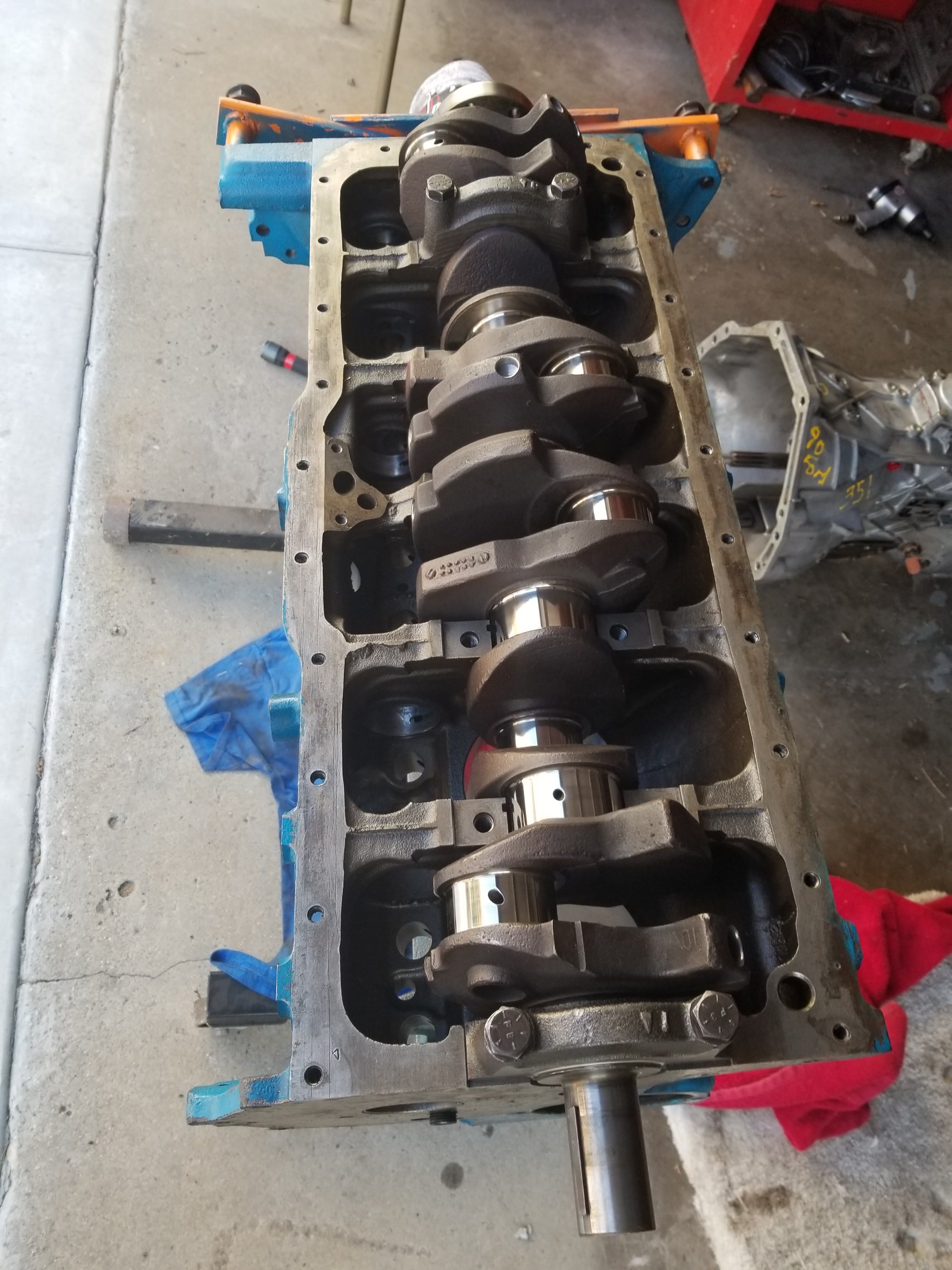
Ten years ago I paid a friend, a pro mechanic, to build an engine. He showed up each day to work with a 12 pack. Engine failed in less than 1k miles. I learned a heap. Some about engines as well. It became a matter of pride to rebuild the engine myself. Ten years passed. Now, after collecting parts, custom cam, cliffy intake, cliffy shorty headers, flowmaster 50 muffler, ZF trans, hydroboost brakes, saginaw p.s pump, braided lines, flywheel, new crank from a 96, pistons from a 351W, rods from a 66 300, molly rings, I started the build. Today I hung the pistons on the block to measure the quench, or distance from top of piston to the surface where the head sits, or the deck. I intend to have the block milled, so that I can know or determine the compression ratio.
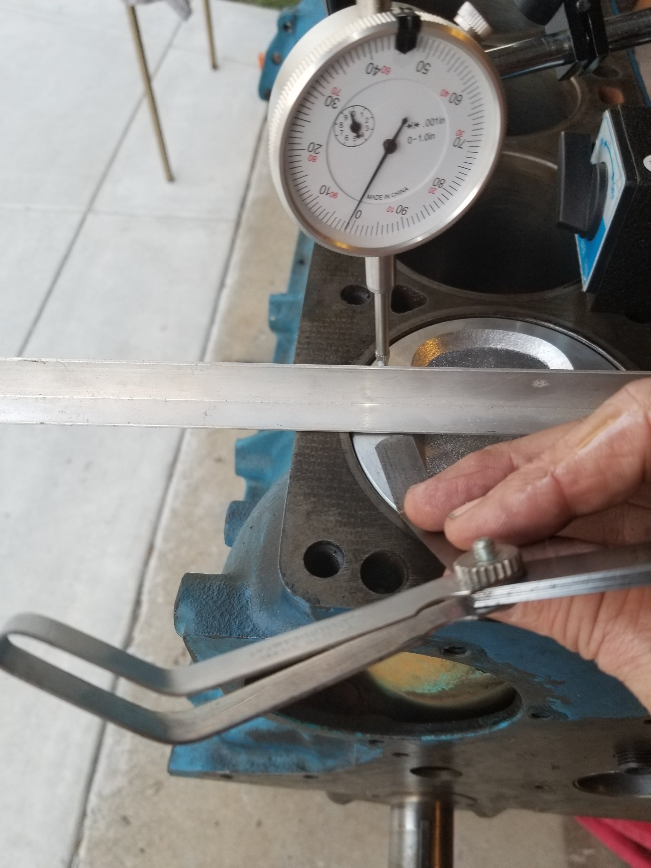
Above, I have a feeler gauge, and am measuring the distance I mentioned. I came up with .024.
Man, I will say that the shop that reconditioned the rods and installed the arp bolts, should have loosened the caps as part of the service. What a bear to get the caps off. I had to clamp them in a vise and pry a 1" dowel in there to get the cap to separate.
For anyone building an engine, you have to follow the golden rule: Always have the crank polished. That is what, I believe, made my engine fail. I had the crank turned, without having it polished afterwards.It shredded the bearings. The crank journals should look like the surface of a mirror. I didn';t know at the time. I do now $$.
I also want to say that the choice of pistons for the 300 is poor. However, if you get the rods from the early 300, from 65-68 I believe, they fit the 351w pistons, and open up a world of great pistons.
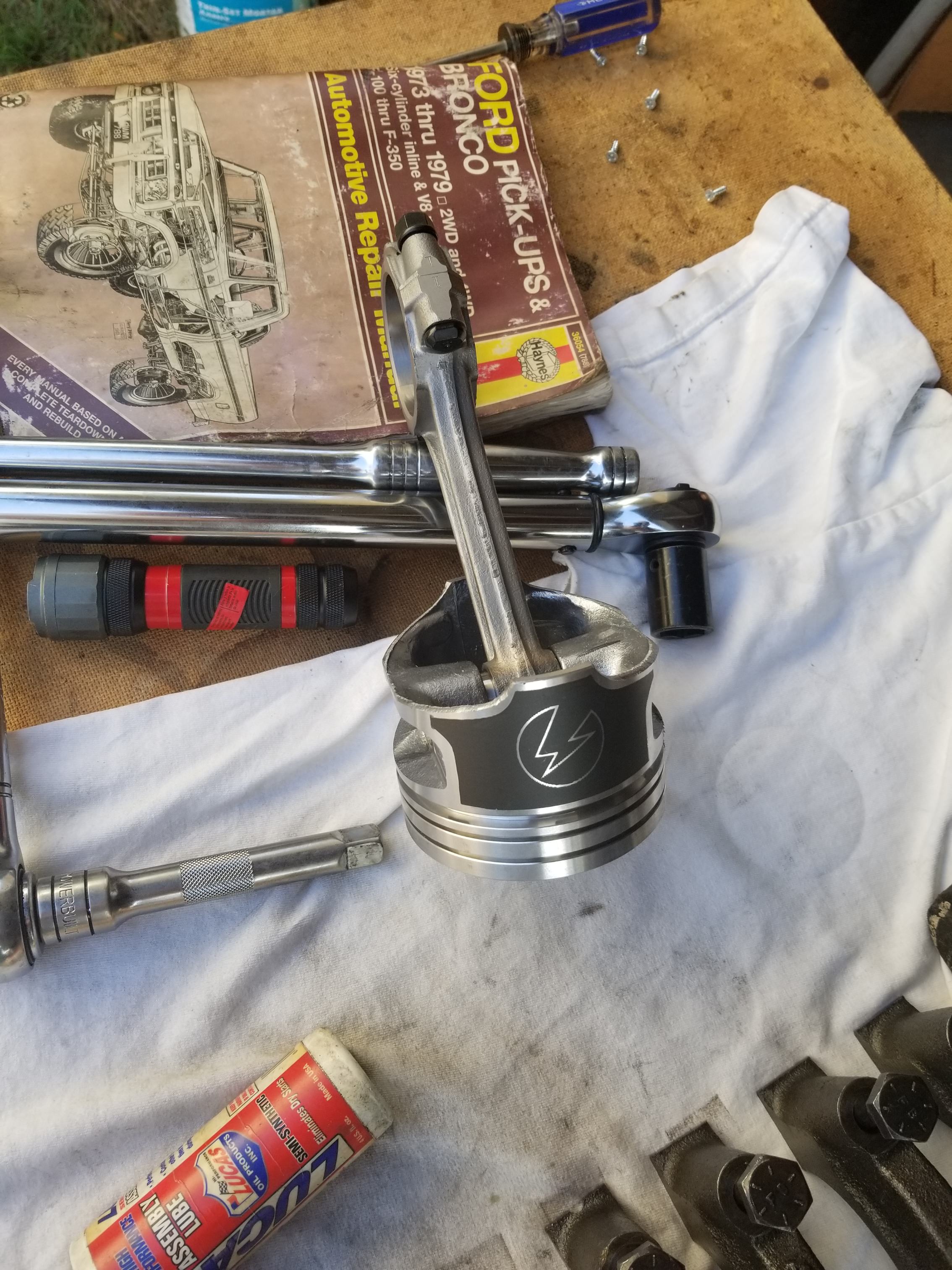
Yes, I'm a Harry Potter fan, so I had my shop lazer etch a lightening bolt into my pistons. Not really. ha ha. I can't wait to start up the engine and hear a loping idle. THAT will be sweet.
Above, I have a feeler gauge, and am measuring the distance I mentioned. I came up with .024.
Man, I will say that the shop that reconditioned the rods and installed the arp bolts, should have loosened the caps as part of the service. What a bear to get the caps off. I had to clamp them in a vise and pry a 1" dowel in there to get the cap to separate.
For anyone building an engine, you have to follow the golden rule: Always have the crank polished. That is what, I believe, made my engine fail. I had the crank turned, without having it polished afterwards.It shredded the bearings. The crank journals should look like the surface of a mirror. I didn';t know at the time. I do now $$.
I also want to say that the choice of pistons for the 300 is poor. However, if you get the rods from the early 300, from 65-68 I believe, they fit the 351w pistons, and open up a world of great pistons.
Yes, I'm a Harry Potter fan, so I had my shop lazer etch a lightening bolt into my pistons. Not really. ha ha. I can't wait to start up the engine and hear a loping idle. THAT will be sweet.
Thread Starter
|
Lead Driver
Joined: Mar 2008
Posts: 7,184
Likes: 382
From: Near Los Angeles
Nor have I checked the rod clearances. I did notice, however, that the Hayes book said the tolerences on the rods were remarkably tight, less than .002, iirc. That surprised me.
Today I just hung the pistons to see how much I needed to have the block milled.
Thread Starter
|
Lead Driver
Joined: Mar 2008
Posts: 7,184
Likes: 382
From: Near Los Angeles
"It's a good practice to verify everything." Absolutely an excellent point. I don't want to take anything for granted. Thanks for calling me on that. It didn't cross my mind. And yes, double yes, confirm before milling the block!! Great point. Thank you.
Moderator
Joined: Dec 2007
Posts: 7,987
Likes: 104
From: Boise, Idaho

Indeed! Very much looking forward to watching this come together. 
I have the same lightning bolt on my pistons. It's good for about 5 horsepower.
I have the same lightning bolt on my pistons. It's good for about 5 horsepower.
Trending Topics
Thread Starter
|
Lead Driver
Joined: Mar 2008
Posts: 7,184
Likes: 382
From: Near Los Angeles
FTE Stories
Ford Trucks for Ford Truck Enthusiasts

10 Things Every Truck Owner NEEDS (2026 Edition)
Michael S. Palmer
Rezvani's Latest Post-Apocalyptic Monster Is a Ford F-150 Raptor Underneath
Verdad Gallardo
Top 10 Most Expensive Ford Trucks Ever Sold on Bring a Trailer
Joe Kucinski
2027 Ford Super Duty Buyer's Guide (Every Model, Engine, & Package)
Brett Foote
Top 10 Ford Truck Tragedies
Joe Kucinski
AEV FXL Super Duty - the Super Duty Raptor Ford Doesn't Make
Brett Foote
Lobo Vs Lobo: Proof the F-150 Lobo Should Be Even Lower!
Michael S. Palmer
Ford's 2001 Explorer Sportsman Concept Looks For a New Home
Verdad Gallardo
10 Best Ford Truck Engines We Miss the Most!
Joe Kucinski

Thread Starter
|
Lead Driver
Joined: Mar 2008
Posts: 7,184
Likes: 382
From: Near Los Angeles
The surface in the dish is very rough. What would be the best way to polish it? For the chambers of the head I was going to polish with well-worn rolls on the die grinder. Is that the way to do it in the dishes as well?

More Turbo


Joined: Nov 2015
Posts: 710
Likes: 111
Get some 1" diameter cartridge rolls that fit on a 1/4" mandrel to use with your die grinder
They should reach the bottom of the dish and be flat with the bottom with the grinder parallel to the top of the piston if the mandrel is long enough.
Use the small rolls for the sides.
They should reach the bottom of the dish and be flat with the bottom with the grinder parallel to the top of the piston if the mandrel is long enough.
Use the small rolls for the sides.
Thread Starter
|
Lead Driver
Joined: Mar 2008
Posts: 7,184
Likes: 382
From: Near Los Angeles
Get some 1" diameter cartridge rolls that fit on a 1/4" mandrel to use with your die grinder
They should reach the bottom of the dish and be flat with the bottom with the grinder parallel to the top of the piston if the mandrel is long enough.
Use the small rolls for the sides.
They should reach the bottom of the dish and be flat with the bottom with the grinder parallel to the top of the piston if the mandrel is long enough.
Use the small rolls for the sides.
Attachment 284293
The bottom photo below is your chamber, pmuller.
More Turbo
Joined: Nov 2015
Posts: 710
Likes: 111
Most of the material to be removed to bring the chamber out to the bore circle line is near the top and as you taper the side towards the valves it just becomes a matter if smoothing out the rough surface.
I used a cone shaped burr for that part of the job and switched to tapered rolls on a mandrel to finish and to do the chamber floor.
Much safer working near a completed valve job with sanding rolls.
I used a cone shaped burr for that part of the job and switched to tapered rolls on a mandrel to finish and to do the chamber floor.
Much safer working near a completed valve job with sanding rolls.