When you click on links to various merchants on this site and make a purchase, this can result in this site earning a commission. Affiliate programs and affiliations include, but are not limited to, the eBay Partner Network.
@brokestroke I forget, what turbos are you going with again? You might be better off swapping the atmospheric over to the passenger side for easier downpipe routing. Since it's an Ex, you can also remount the batteries in the rear.
Also, please tell me you're going to stick those drawings up on the fridge with magnets.
Unfortunately frame mounting the batteries is not an option. The main reason is because the batteries on the frame will be subject to harsh elements...mud, snow, water, ice, dust.
I don't see there being room under the hood on the driver side. Remounting both batteries along the frame rail may give more room but I'm not convinced it's usable room unless you're planning to move almost everything under the hood. If you try to drop the down pipe on the driver side you have to contend with the drive shaft. I've done that on a 5.0 ranger swap and it was tight with 2-1/2" pipe. I ended up having to oblong the pipe to give me a comfortable amount of clearance. I would go back to the drawing board.
The issue I see with mounting on the passenger side is there wont be any room for a sufficient air filter. On the driver's side, removing the battery and the air filter opens up a decent space..
Brokestroke, what is the inlet size you are trying to match to an air filter? Is it 4" on the HX35?
What is the estimated length or space constraints you feel you will have on the passenger side for an air filter?
If you think that having the turbo on the passenger side will work better for tube routing, perhaps a solution can be identified in order to make that happen. Just spit balling here and not asking you to change your drawings quite yet.
There are a lot of 4" inlet filters available that have a somewhat low profile, like this one for example. It is 5.5" in length.
I don't know what the CFM requirements would be from the compound turbo setup and I don't know what the CFM rating is of the filter, but since you are in the early stages of design I thought I would throw this on the table. There are other designs as well that may offer a better fit for that space.
A filter like this for example.
Having the filter on the passenger side brings along a new set of challenges, but it might be something worth considering. Either way, I look forward to how this project will progress.
Also, that clearance/articulation gained ONLY by removing the front sway bar is dramatic to say the least. I would not have expected that much and would have bet against it.
Unfortunately frame mounting the batteries is not an option. The main reason is because the batteries on the frame will be subject to harsh elements...mud, snow, water, ice, dust.
What I meant was mount the batteries in the back inside the cabin like what all the newer vehicles do. The vacuum pump and tank are more easily moved that trying to connect the turbine outlet of the atmospheric turbo to the exhaust on the passenger side I think. Or are you moving the exhaust too? Hey here's an idea: do a side dump exhaust just behind the front wheel. That or a hood stack. Keeping the atmospheric turbo on the driver side makes more sense then.
Just a random thought. If you used the passenger side would it be possible to run the DP down through where the battery tray is now? Go straight down somewhat through the fenderwell area. Maybe even consider turning the turbo with DP side down? Probably a stupid idea from my couch but wanted to at least share it in case if spawned another concept.
Edit before even posting.... I think the oiling for the turbo requires a certain range of angles so turning it up on its end is probably completely off the table and a stupid idea.
Edit after posting: it seems FTN beat me to the fenderwell dump thought.
Trying my hardest to figure out how to route everything. Pipe routing/oiling is tricky but can be done, batteries can be shuffled to an extent without issue. Basic things come to mind like air filters. Sure I can stuff a little air filter in there and it will work. Real world use...not going to work very well, using an air filter HALF the size of a 6637 with a turbo that is MUCH larger than the stock turbo. Or a specialty filter that is $80+ with moderate filtration at best that needs maintenance at twice the interval a 6637 does. Things to think about.
If you don't mond a long convoluted tube from the turbo to the air filter, a 6637 will fit behind the bumper I think.
Snow and mud comes to mind but we'll see.
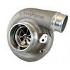
Got a Hydra installed on the Ex. Running a single file, 40hp Daily Driver. Got rid of it's laziness and retained the smooth shifting it has stock. Also the first time I have ran tuning with this gtp38 setup and it spools instantly. The turbo specs are; gtp38 with .84ar, ATS ported compressor housing (the old purple one, 4" inlet) with a KC s300 turbine, billet 9+0 compressor wheel (same blade count as stock) and a 360* thrust washer. Starts spooling alot sooner than my S366 but can feel it loosing steam at upper RPM. Will get some gauges on it shortly but I know it is a warm turbo. Waiting for the right time to swap in the 1.0ar and bellowed up-pipes.
Another thing I never touched on is the transmission cooler. This Ex is a 2000 and did not come with the transmission cooler in the radiator, instead just a tiny air-oil cooler...unfortunately. My "donor" is a 2000 v10 that came with 2 coolers. The radiator is leaking so no swapping it over, but it has the "large" V10 air-oil cooler. So I piggy backed the V10 cooler into my cooler system. Was able to scavenge the cooler lines from the V10 and run the cooler behind the grill. Not as optimal as have a cooler in the radiator (imo) but should do just fine for my needs.
The two added together basically equals a 6.0 cooler +/-.
The two added together basically equals a 6.0 cooler +/-
Not really.
And while the photo showing all three coolers together would seem to indicate that the surface areas of the V10 + 7.3L coolers combined approximates the surface area of the 6.0L cooler adjacent to them, the same photo also illustrates why similar surface area in total does not make them at all equal.
The 6.0L is one cooler, where all the fluid entering into it flows simultaneously across it in parallel. The entry and exit distribution headers are also more voluminous.
The V10 + 7.3L coolers are sequential, where all the fluid flows serially, first through one cooler, and then through the next cooler. This serial flow path can potentially reduce flow rate, but may not necessarily reduce flow rate below Ford's minimum specified flow rate, so it is best to check.
Since Ford calls for a minimum of 1 gallon per minute of fluid flow of transmission fluid through the cooling circuit at idle, using a one quart graduated container and allowing the engine to run for 15 seconds after disconnecting the return line to the transmission following the last cooler in series should be enough testing to determine adequate fluid flow.
And while the photo showing all three coolers together would seem to indicate that the surface areas of the V10 + 7.3L coolers combined approximates the surface area of the 6.0L cooler adjacent to them, the same photo also illustrates why similar surface area in total does not make them at all equal.
The 6.0L is one cooler, where all the fluid entering into it flows simultaneously across it in parallel. The entry and exit distribution headers are also more voluminous.
The V10 + 7.3L coolers are sequential, where all the fluid flows serially, first through one cooler, and then through the next cooler. This serial flow path can potentially reduce flow rate, but may not necessarily reduce flow rate below Ford's minimum specified flow rate, so it is best to check.
Since Ford calls for a minimum of 1 gallon per minute of fluid flow of transmission fluid through the cooling circuit at idle, using a one quart graduated container and allowing the engine to run for 15 seconds after disconnecting the return line to the transmission following the last cooler in series should be enough testing to determine adequate fluid flow.
Why I used the term +/-
2 oil-air coolers shouldnt change flow anymore than a factory oil-water combined with an oil-air much like the later year trucks.
On another note DieselSite recommended running multiple coolers in line with each other. My F350 has a DieselSite 4r100 and 3 coolers, stock radiator and stock oil-air along with a second oil-air mounted behind the grill.
I believe Ford offered the transmission OTW cooler via a modification for the 2000 MY that didn't initially come with it when the later models came out with it from the factory. That is most definitely not the case anymore, but I am fairly certain that part of history has been said here before, but I could not find the source...
Does DieselSite recommend running multiple coolers in line if the OTW radiator cooler is still installed?
Do they recommend removing the OTW radiator cooler from the plumbing of their 4R100 cooling system?
I have seen Mark K mention something along the lines of the quote below many, many times when discussing the OTW cooler in the radiator.
Originally Posted by Mark K
It only makes sense if you don't work your truck. If you plan to tow with it, plan on a new transmission really soon. You'll cook the trans if you remove the most effective transmission cooler.
Perhaps this advice is negated by running multiple coolers in line with each other, I don't know. Just thought I would bring the advice from a reputable source to light that I have seen many times.
Just some things to think about or discuss if you feel the need is there.
This Hennessey Takes the Expedition Tremor's Off-Roading Capability to the Next Level
Slideshow: The VelociRaptor Expedition gains a lift, upgraded suspension, Brembo brakes, and trail-ready equipment while retaining the stock 440-horsepower EcoBoost V6.
Rezvani's Latest Post-Apocalyptic Monster Is a Ford F-150 Raptor Underneath
Slideshow: Called the Fortress, the 850-horsepower pickup combines Raptor underpinnings with military-inspired features, survival equipment, and a starting price of $285,000.