When you click on links to various merchants on this site and make a purchase, this can result in this site earning a commission. Affiliate programs and affiliations include, but are not limited to, the eBay Partner Network.
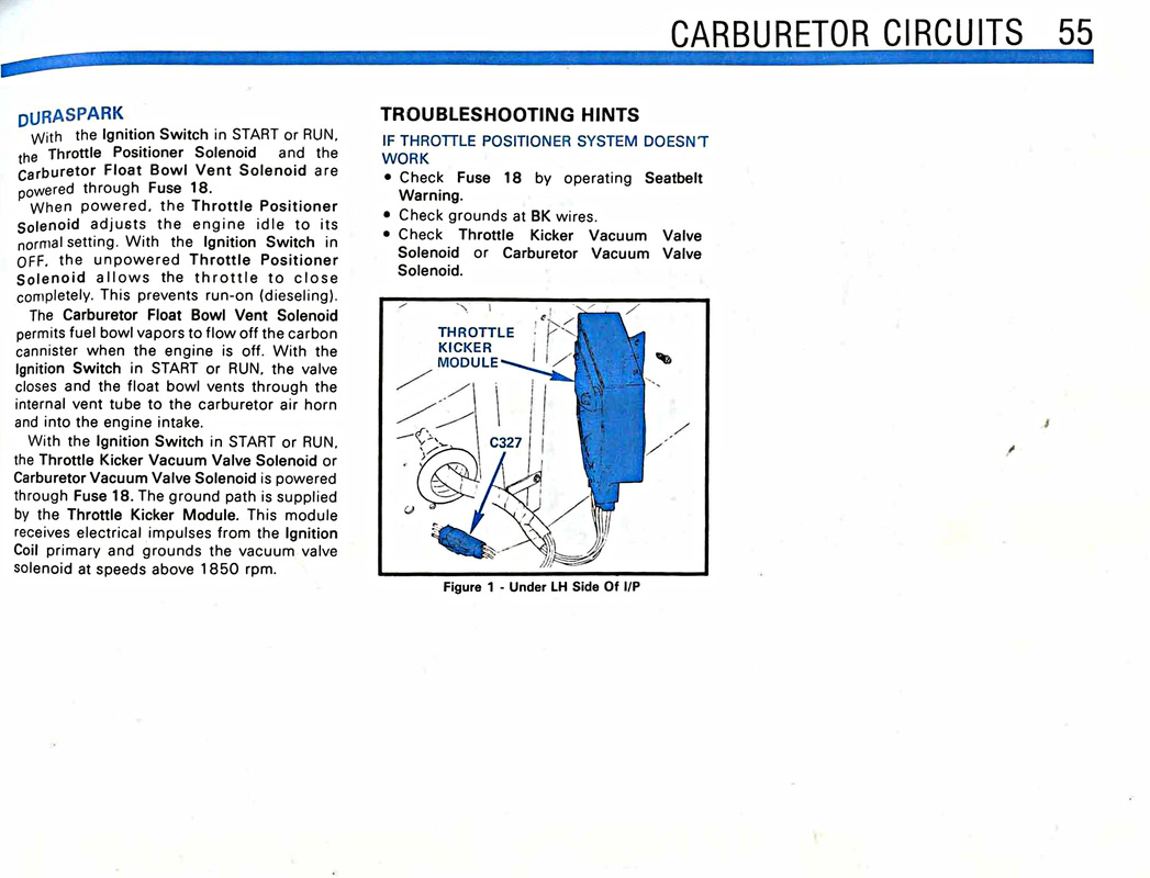
Here is a picture of C327. It's under the dash on the driver's side. Look for that large grommet, that may help pinpoint it. If you find it, look for the red/lightgreen wire.
Ok, I just uncovered my cab and dug out all the pieces of my harness and mapped every connection from the ignition module. Now this is on my 82 and I haven't compared those to the latter model wiring yet, but I will. I unwrapped my entire harness to follow the wires and I used a multimeter to verify point a-z using continuity. Colors maybe a little off due to fading, but I guessed the best I could. This will at least let you compare mine to your existing wiring. Will post this heads up, then edit post with my findings(wifey pushing a hotspot for me from her phone).
*EDIT*
Here's what I came up with.
Red from module - white with blue dashes goes to pin 11/16 on ignition switch
White from module - red with blue stripe goes to pin St/32 ignition switch
(I believe the individual wires are numbered at the switch, but each pin looks to have two numbers as well as wires going to them)
Green from module - green 1 - coil negative
green 2 - goes into two prong plug - green with yellow stripe goes to pin 11 on instrument cluster
unused side of two prong plug is black with green dashes and goes to pin 12 on instrument cluster
Black on module - distributor
Purple on module - distributor
Orange on module - distributor
Coil positive goes to four prong plug into red with green which hits a factory splice wires out of that splice as follows:
brown with pink stripe goes to pin 12/262 on igntion switch
and
pink with 2 green stripes labelled "resistor do not cut" leads into another splice:
red with double blue(assume another resistor) goes to pin 11/16 on ignition switch(which is same pin as the red from the module)
and
green with red which runs across inside of cab and out the firewall and runs into "S" pin on voltage regulator
the other three prongs on the 4 prong the red from coil goes to are
2 red with blue stripe goes to red with yellow dash, mine was cut and folded back into the harness shroud, will have to look at diagrams to see where it went(guessing ballast resistor. Mine the wires rotted off of it and I have since spliced a new "horseshoe" connector in and I'm thinking that wire went to resistor then to coil +[red]. But that was over a year ago and I honestly can't remember). Also, I didn't document it properly in my notes, it was cold and dark and I was in a hurry, but this wire is fed from one of the factory splices that come off the coil + but I'm only 95% sure on that, can verify if need be.
3 white with red stripe has a single round connector, gonna be oil or temp sender wire(have to verify on the diagrams) and goes to pin 10 on instrument cluster
4 red with white stripe has a single round connector, and it's the other one(oil or temp) and goes to pin 6 on instrument cluster.
Sorry if this format is confusing, it's the best I could come up with. I'll compare it to your harness when I get a chance.
I think what this is all boiling down to is the IGN CIRCUIT power supply. The OP does not see a power wire with a DS type connector. The vehicle is (was) TFI so there will be no DS connector included the vehicle harness. The IGN is now free-standing and in no way should have to be tied into any other circuit (EEC)
The BAT VOLT IGN supply must be identified on the IGN SW and run from there to the IGN MODULE. A DS connector is available.
The only circuit that should now need to be active is BAT off the IGN SW. WHITE is not important and can be connected later.
You need to find the power source for the ORIGINAL TFI and draw it from there. The correct WIRING DIAGRAM (year) will give you that information. The PAINLESS supplied resistor will protect the DS II coil.
KULTULZ Thanks for the time and info your giving me but I'm getting confused as to what your telling me as opposed to what I've already done. The drawing I previously posted was crude but its showing exactly what I've got as close to Painless's instructions as I could get, if you would take a look at it and tell me (like your talking to a 5 year old) which wire goes where and what I need to do to wire it your way...sorry for the trouble my friend
Usually followed by a pool cue across the nose bridge ...
Thanks for the time and info your giving me but I'm getting confused as to what your telling me as opposed to what I've already done. The drawing I previously posted was crude but its showing exactly what I've got as close to Painless's instructions as I could get, if you would take a look at it and tell me (like your talking to a 5 year old) which wire goes where and what I need to do to wire it your way...sorry for the trouble my friend
Sorry about that. What you have drawn out is correct. What I meant by 'free-standing' is the PAINLESS HARNESS is usually used for DS RETRO-FIT, that is (was) an older breaker points system and install is much simpler.
What I am trying to get at is in one of your previous posts, you had no DS feed harness connector. There is none with a TFI. You need to find the correct power wire from the IGN SW and run that down to the ICM. The actual connector (female --- er male - it has been awhile) is available to allow a simple plug-in.
You are not a 5-year old. You have a vehicle which was previously butchered. That is why shops shied away from it.
If this does not help, yell at me again.
EDIT -
I was referring to an earlier post.
To wit -
Originally Posted by dallasf150
Could someone tell me what the white/pink wire is for, its in the stock male 321 plug at the top but the module plug doesnt accomodate it, the stock female it plugged into has a diode then turns green/white and disappears into the loom into the firewall,this wire AND the red/ Lt blue wire shown both have continuity to the push on wire to the starter relay.
DURASPARK - ECHLIN EC72 (NAPA)
You will see three leads (pins). This is meant to service more than one version of DS. Simply remove the third pin.
I now have the plug your showing, the current setup I have has a keyed source (blue/white wire) spliced to the input side of the ballast and back to the module,the red/blue wire beside it is connected to the "S" on solenoid and cranks the engine well, the brown from the Painless wires over to the "I" has power when the key is in the "on/crank" position, that part seems to be working fine just no spark, if I used the Painless plug wouldn't it be the same but id have to connect another power supply like the blue/white?
I now have the plug your showing, the current setup I have has a keyed source (blue/white wire) spliced to the input side of the ballast and back to the module,the red/blue wire beside it is connected to the "S" on solenoid and cranks the engine well, the brown from the Painless wires over to the "I" has power when the key is in the "on/crank" position, that part seems to be working fine just no spark, if I used the Painless plug wouldn't it be the same but id have to connect another power supply like the blue/white?
OK, I think I see the problem. When did you get the connector?
Ok,
and
pink with 2 green stripes labelled "resistor do not cut" leads into another splice:
red with double blue(assume another resistor) goes to pin 11/16 on ignition switch(which is same pin as the red from the module)
and
.
Can you measure the length of the pink wire, "resistor do not cut".
Also was part of this wire coiled up somewhere, could you see this coil of wire by looking under the dash near the brake peddle, This is something I have looked for but never found,
Thanks, Jim
I now have the plug your showing, the current setup I have has a keyed source (blue/white wire) spliced to the input side of the ballast and back to the module,the red/blue wire beside it is connected to the "S" on solenoid and cranks the engine well, the brown from the Painless wires over to the "I" has power when the key is in the "on/crank" position, that part seems to be working fine just no spark, if I used the Painless plug wouldn't it be the same but id have to connect another power supply like the blue/white?
It seems I was wrong OK'ing your WIRING DIAGRAM.
Yours is shown below -
Now view the PAINLESS schematic-
You CRANK/START circuit is OK at the STARTER RELAY because it cranks.The BLUE WHITE IGN PWR is OK as it matches the 1985 DURASPARK schematic coming off the IGN SW. I think you will find your problem comparing yours and the PAINLESS schematics at the COIL CONN.
Check the routing of the BROWN WIRE compared to PAINLESS..
Can you measure the length of the pink wire, "resistor do not cut".
Also was part of this wire coiled up somewhere, could you see this coil of wire by looking under the dash near the brake peddle, This is something I have looked for but never found,
Thanks, Jim
The pink with double green labelled "resistor do not cut" is under the hood, coming from the main bundle out of the firewall on the left side. Mine looked brown, it being dark out didn't help, I had to clean it up to see the color and that's when I noticed the writing. It's not very long, I'll measure tomorrow. That part of my harness was wrapped up pretty good. It'll likely be in the thickest portion because of the bulky factory splice.
What I am trying to get at is in one of your previous posts, you had no DS feed harness connector. There is none with a TFI.
The above is incorrect. All the plugs are there in the factory TFI harness, whether you have EFI or a computer/carb type TFI. It's all right there in the diagrams. Now whether his plugs had been cut out by someone else I don't know.
Don't let me stop you from helping though. I layed it all out in some previous posts, but apparently I do not explain it well enough, I am not getting through. That is ok, I have people give me a blank look face to face sometimes when I am trying to explain something, it must be some fault I have. So keep going, but he may need some outside help from a friend or a relative to help him get going on it.
Sorry if this has already been dealt with, but I did not see it so wanted to be sure.
For your negative battery cable, the main cable should be to the engine block (closer to the starter is better, but...) but there should also be an additional wire from the battery to the body, usually at the fender skirt or fender top adjacent to the battery. At least a 10ga wire.
I remember you said that some things got better when you added a ground wire from the engine to the frame, and if you don't have a main body ground this could be why.
The factory wiring will have a ground wire directly to the body, but also a second one from the back of the intake manifold to the firewall. If you no longer have this one (you did change the manifold, and we haven't seen any pics of the whole setup, so thought I'd ask) then you should add it back in.
Sometimes the factory part is a bare braided strap, sometimes it's braided and covered by a black vinyl coating, still other times it's just a Black wire. Usually at least 10ga but I think the braided ones are rated slightly larger than 10ga.
Anyway, grounds are just as important as 12v positive wires are.
And to this previous image you posted, you have since moved the Red w/blue wire over to the S terminal I believe you said. Is that correct?
Originally Posted by dallasf150
What about the main power to the ignition switch wire?
On the diagrams for the different years posted up already it's listed as a Yellow wire (for trucks with lights instead of gauges) and a Green wire (for trucks with an ammeter). Do you still see a Yellow or a Green wire with a fusible link at the end nearby?
And if gauges, does your '86 have a volt-meter in the dash, or an ammeter still? I was thinking that around this time Ford changed to a volt-meter, but I never really knew what year got the change. Just that it happened.
For reference earlier trucks had a large Black, or Black w/yellow trace wire (about 10ga or so?) connected to the battery side of the starter relay that carried all the power to the cabin accessories. I don't see that in the diagrams so they may have changed it, or maybe they leave it out of those particular drawings because it's shown on a different set of diagrams?
If you have one of those large Black wires hanging around somewhere, let us see it and maybe it's something that has to go back to the starter relay battery side. Right now I'm not sure what the existing three or four wires are. Looks like a couple of red ones and a blue one, but were they there before, or are they part of your new wiring setup? They look like older wires but I don't remember seeing things like that at the relay personally.
The grounds I mentioned may, or may not help your current issue, but they are important for the overall health and well being of the electrical system so should be maintained.
I see what looks like a MAP (manifold absolute pressure) sensor there just to the right of the starter relay too. That's exclusive to the EFI setup so can be removed as well. Might as well make sure at least that the vacuum hose attached to it does not connect to anything on the engine at least. Removing it will leave you with one less hose to hunt down a connection for.
Oh yeah, one last thing...!
Yeah, right. Is there ever just one last thing? Not!
You said your engine is an '86 5.0 model and you used an '85 distributor?
If so, that's probably just right, but were the truck 5.0's also roller cam equipped in '86? Just checking, because I don't know. The '85 Mustang distributor would have a steel gear for compatibility with a roller cam.
Not sure what gear an '85 truck distributor would have, or if it's the same. Since nobody but me brought it up, I figure everyone else knows the answer and you're using the right combination of parts. But I didn't know so wanted to bring it up.
The above is incorrect. All the plugs are there in the factory TFI harness, whether you have EFI or a computer/carb type TFI. It's all right there in the diagrams. Now whether his plugs had been cut out by someone else I don't know.
Now just a cotton-pickin minute...
You are saying the TFI harness on an 86 TFI has the same connectors as an 85 DS harness?
Now my head is starting to hurt.
Had he salvaged or found a NOS 14289 harness, the schematic you showed may have worked. The harness he has is an aftermarket designed to make a DS II system more easily retro-fitted to a points style system. It (this current changeover) requires an intermingling of systems (without burning the truck down, hopefully).
Rezvani's Latest Post-Apocalyptic Monster Is a Ford F-150 Raptor Underneath
Slideshow: Called the Fortress, the 850-horsepower pickup combines Raptor underpinnings with military-inspired features, survival equipment, and a starting price of $285,000.