When you click on links to various merchants on this site and make a purchase, this can result in this site earning a commission. Affiliate programs and affiliations include, but are not limited to, the eBay Partner Network.
DEGREEING THE DAMPER
TURNING YOUR HARMONIC BALANCER INTO A USEFUL TOOL
Your harmonic balancer will be a useful tool for your engine if you add some timing marks to it. If it is marked at three points, exactly 120 degrees apart and aligned with the TDC mark on your balancer then it will be easier to set valve lash, check timing scatter and even verify advance/retard in the cam. In addition, by adding an additional mark exactly 30 degrees before #1 TDC you can check total advance with a timing light.
In this exercise I will be using a harmonic balancer from a Ford six, but the principles are the same regardless of the brand of engine. And the only tools needed are a compass, a pencil, a combination square, and a ruler.
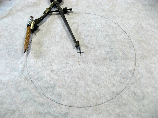
Start with a piece of adhesive backed paper. I used paint shop masking paper but any sticky paper will do such as cabinet shelf paper.
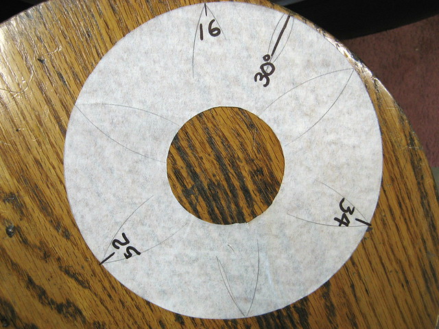
1. Measure the diameter of your damper. On the sticky-backed paper scribe a circle that is about 1/16” smaller in diameter than the outer ring of the damper. DO NOT DISTURB THE COMPASS ADJUSTMENT SCREW FOR THIS NEXT STEP.
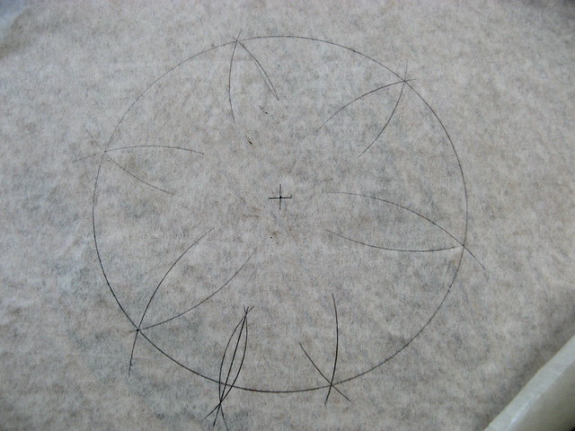
2. Move the point of the compass to the circumference of the circle and swing an arc to intersect the circle at two points. Then at those two intersections swing two more arcs . Keep doing this, moving around the circle until you have the “flower petal” pattern shown. If you have not disturbed the compass setting from Step 1 all the arcs will join together as shown. Each will be spaced exactly 60 degrees apart from its neighbor and every other point will be 120 degrees apart – EXACTLY how much the crank throws are separated on the crankshaft.
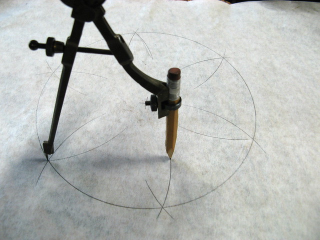
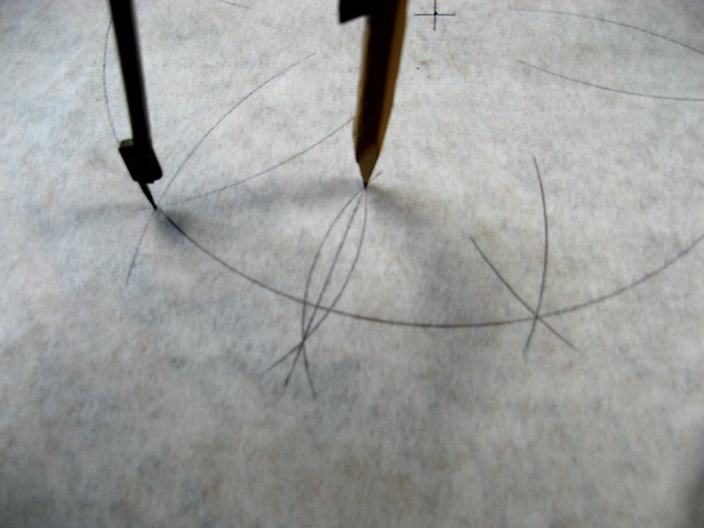
3. This next step makes the damper even more useful – for checking total centrifugal advance. Reset the compass to a smaller opening just a little larger than half the distance between two adjacent points. From one of the points scribe an arc through the diameter. Then move the compass point to an adjacent point and repeat the scribing so the arc intersects the first arc. Congratulations, by drawing a line through the two intersects you have just bisected the 60 degree arc, creating two 30 degree arcs.
4. Now cut out the pattern you just created and mark it as shown at three equally spaced places, putting the “#1 / #6”mark just 30 degrees counter-clockwise to the bisect line as shown. Cut a hole in the center so you can get a socket wrench on the bolt to turn the crankshaft.
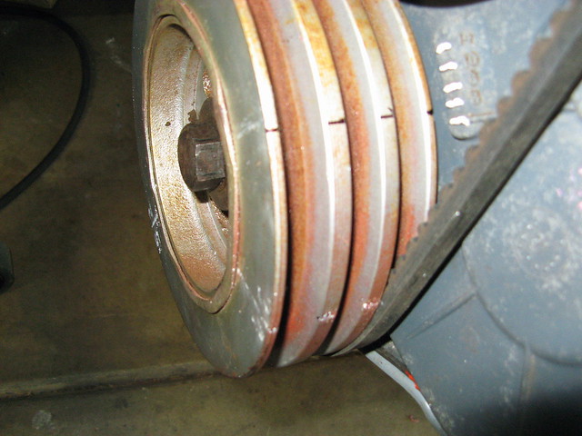
5. Find the timing mark on your damper and verify TDC. [Note: some dampers have more than one mark so verify by checking TDC you have the correct one.] Using the combo square mark a line across the damper so you can easily align the #1 / #6 mark on your pattern with it.
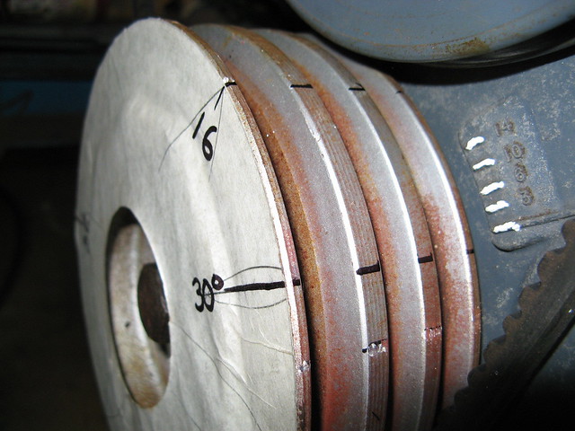
6. Place the pattern against the front of the damper and align it precisely then press it in place. You can now transfer the locations of your cylinders' TDC on to the damper.
The 30 degree mark is useful for setting total advance with a timing light. Increase RPM until the centrifugal advance is “all in”. If your total advance is 34* BTDC, for example, then the 30 degree mark will be aligned with the 4 degree mark on the timing tab. So now your damper can be used for timing your engine and setting your valves easily.
First of all... I like the last two tips from FTF. But apparently I've liked too many contributions by FTF and this site thinks I'm being selfish with my reps
Second, my trick stems again from the fact that I don't have the Ford specified tools - this time, I was missing tool T65P-6701-A. Specifically for installing the rear main seal. My solution was to use the old rear main seal and the flywheel as a pressing tool.
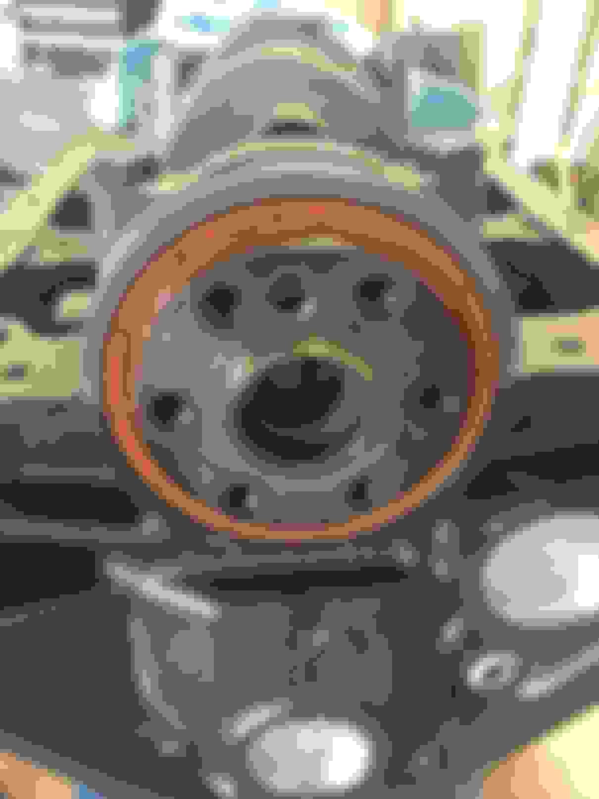
I started the new seal by hand as far as I could (basically just over the crankshaft OD). Then I lined up the old seal - flipped 180 degrees so the flat was pressing on the flat, and started the bolts through the flywheel to hold it in place. I of course coated the new seal with engine oil first, and had to readjust the alignment of everything after snugging the flywheel bolts (see first pic). Then I basically took my sweet time tightening each of the 6 bolts little by little - making sure the new seal was going in straight vs. lopsided - until the new seal was seated. As it turns out, the seal was fully seated (maybe not so coincidentally) when the flywheel bottomed out on the crankshaft face. I double-checked this before removing the flywheel, installing the inspection cover (I remembered!!!) and then re-installing the flywheel and torquing the bolts to spec.
By the way, if AB reads this: your thread reminded me to use thread sealer on the flywheel bolts
Here is a shot from when the flywheel bottomed out, and the last pic is fully installed. Feel free to tell me if I royally eff'd this up.
Pick your poison, I guess. In my opinion (haven't tried it), yes - you can do it without pulling the motor. You will need a large enough gap between engine and bellhousing to work in (6+ inches???) which would mean disconnecting the driveshaft at one end, detaching the trans mount from crossmenber or from trans, and moving the trans back. Or, detaching the engine mounts and picking the engine to move it away from the trans (enough clearance to the radiator???) You have a manual trans, I see, so I'm not sure how that might complicate things.
If you have a one-piece rear main seal, there should be no need to remove the oil pan. Just pick out the old seal, and use it as shown above (with the flywheel) to press the new one in. If you try it, and are successful, let us (me) know. I'm interested!
On my 68 F250 4x4, with a 300 IL 6, I torqued the flywheel bolts to 85 and the clutch to 70... hope this helps...There might be torque specks at Fordification.com
I rotated the cam and went through all of the lifters. Once they were on the heel, I put them at zero lash and then gave them a quarter turn. One of the big mistakes I've read is to do the old trick of spinning them while you tighten. With how smooth things can be, or different grip strengths, they might "tighten up" at different times depending on both the pushrod/lifter and the person. Move them up and down an feel them 'click' between the rocker and the lifter. Once they no longer click (which will be sudden) then they're at zero lash.
Interestingly, I found that you really only need to turn the engine twice to adjust the rockers. At TDC on the compression stroke, you can adjust:
You'll notice that you can do the #3 Exhaust and #4 Exhaust on either one. I saw this posted somewhere online and found it hard to believe, so I went through my cam with the exact degrees of rotation, lobe offsets, duration, etc. and confirmed it. Basically, most tests make SURE it's on the heel because cams are all different. But this one is 300 specific. Even if a lobe is only 5� past being open, it's completely closed and is on the heel.
That said, after I fired mine up, I rechecked it with the alternative method. While it's running, loosen each rocker one at a time until they start to click. Then, tighten it until the clicking stops and give it a quarter turn. It can be a bit messy, which is why I have a second cover with the top cut off, but it works super well.
Great information for those of us with 6's.. Thanks amigo. I got my cam, lifters, pushrods, and valve springs and headers from Clifford's, in Ca. 6 years on the motor now, not an issue with anything motor or mechanical. Solid, purr, at a 750 rpm idyl thru 4000, although I don't go there much. 2600 rpm is 66 mph on my GPS.. although, the old spedo says 54 mph... I believe the GPS
Rezvani's Latest Post-Apocalyptic Monster Is a Ford F-150 Raptor Underneath
Slideshow: Called the Fortress, the 850-horsepower pickup combines Raptor underpinnings with military-inspired features, survival equipment, and a starting price of $285,000.