When you click on links to various merchants on this site and make a purchase, this can result in this site earning a commission. Affiliate programs and affiliations include, but are not limited to, the eBay Partner Network.
You probably could, if you had a 3 or 4 position rocker switch (can't recall if my old one had a neutral position, been a while).
However, if you're having trouble with the switch, I would just buy a new switch and fix it right. You will always know what drive mode you're in, and it will function as intended.
The issue with a rocker switch, and why they aren't used on many vehicles, is that it's too easy to accidentally bump it out of the intended position. A rotary switch, such as the stock one, are harder to accidentally bump out of position.
If you really do want to replace it with something else, I would recommend a multi-position toggle switch, but I don't know if it would do what you want, since one position is usually reserved for 'off.' IIRC the 4wd switch always has power to it, to command the servo to the correct position on the t-case.
I was able to find the electrical schematic and it looks like I will need a SP3T switch with ON-ON-ON positions. They make these switches but you can also take a DPDT switch and "convert" it to a SP3T switch.
The current switch works fine, my reason for changing is more to "clean" up the look some and consolidate switches to one or two areas, as well as update some of the technology. My plan would be to keep the original connect body, so that if it doesn't work I could replace it with the original, or if the rocker switch is an issue like you stated.
Here is what the 4WD mode selector switch schematic looks like.
So just need to determine the resistance for each position.
How�d you do that? I looked into it before but the consensus seemed to be it would take a fair amount of work if not including some resistors.
It wasn't too terribly difficult once you have the service manual to verify that there are resistors. So you ohm out your switch to determine what resistors are needed, and then get an ON-ON-ON switch. It took a little bit of thinking, but not terrible. I will post an exact step by step in my build thread.
I was able to figure this out and decided to share this with everyone else. @Sous
You are going to need wire, connectors, a SP3T On-On-On switch, and three resistors (360 Ohm, 1100 Ohm, and 3900 Ohm).
Here is the OE wiring setup
The light blue with red tracer supplies power to the lights, turns on with illumination switch.
The black wire is the ground wire for the lights.
The dark blue wire is the power out from the ESOF mode selector switch.
The white with light blue tracer is the supply power for the ESOF mode selector switch.
The way the system works is 12V is supplied to the switch and them the GEM (Generic Electronic Module) uses the amperage that is returned to determine what mode has been selected. I won't go into how the actual actuator system works but I'll give a short explanation of how the switch works. We know from Ohm's law that V (Voltage)(Volts) = I (Current)(Amps) * R (Resistance)(Ohms), manipulating the equation we can see the amperage changes as we select a different mode (I =V/R). Using a nominal 12V: in 2Hi the GEM is looking for ~3.1 mA, in 4Hi it's looking for ~11.0 mA, and in 4Lo it should see ~29.6 mA.
So with the basic logic explained we can get to the actual installation of the new rocker switch.
Pull the old ESOF switch out and remove the connection. I cut it out entirely, but you could splice into the existing wires to be able to switch back to the old ESOF switch or you could get the corresponding female connector and make it directly plug in.
1. Per the OP request, I've moved this thread from 1999-2016 subforum to the 1999-2003 subforum
2. Per member request, I've included this thread into the 7.3L Tech Folder, under the transfer case category
3. For continuity's sake, and to incorporate the OP's link to a video on this mod posted in another thread, I've moved those posts to this thread.
4. I would like to request that @ZachT93 post a photo of his dash panel where the new switch is. Presumably, the point to converting the OEM switch to a rocker switch was to be able to fit a small switch panel with similar rocker switches in a row in an area on the dash panel that is the nearest and most optimal reach to the driver. This thread is missing a photo of the end result of all the effort in "making the switch" (ha ha).
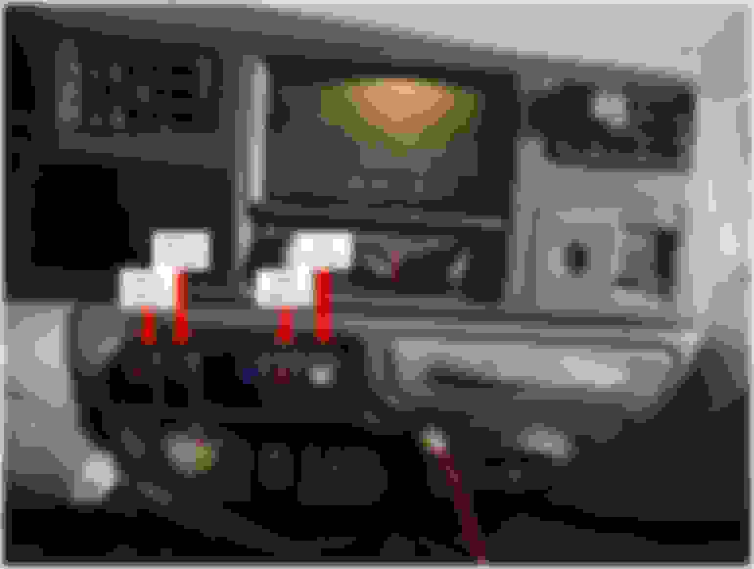
Per request, here is the finished product from this mod. I still have more work to do, and changes to make on the truck. Ultimately, I can use this rocker switch setup to convert the system to a PLC system. I would like to incorporate the HVAC, stereo, all switched controls, and accessories through one platform, but that'll have to wait.
Edit: Picture updated to include explanation of each switch
Per request, here is the finished product from this mod. I still have more work to do, and changes to make on the truck. Ultimately, I can use this rocker switch setup to convert the system to a PLC system. I would like to incorporate the HVAC, stereo, all switched controls, and accessories through one platform, but that'll have to wait.
Shall we assume that by "PLC system" you mean incorporating a Programmable Logic Controller?
And don't hold back now... which switch is now your ESOF switch?
Shall we assume that by "PLC system" you mean incorporating a Programmable Logic Controller?
And don't hold back now... which switch is now your ESOF switch?
Switch five (5) is the transfer case controller, switch six (6) is for future 2Lo mod.
Yes, program logic controls. I have used Danfoss logic controls in the past and will likely use this for this project. So ultimately all the rocker switches will be gone, the head unit should be gone, no more gauges (beside standard instrument panel), integrate the climate controls into the controller, and eliminate all switches on the interior besides the window switches.
Per request, here is the finished product from this mod. I still have more work to do, and changes to make on the truck. Ultimately, I can use this rocker switch setup to convert the system to a PLC system. I would like to incorporate the HVAC, stereo, all switched controls, and accessories through one platform, but that'll have to wait.
Edit: Picture updated to include explanation of each switch
Nice setup. For custom switches you could check these guys out and see if you could get some that label each for function..... https://rockerswitchpros.com/
I have the manual F650 dash that I still need to install. Using to install my auxiliary fuel tank control/gauge along with Airlift airbag gauge/controller.
Rezvani's Latest Post-Apocalyptic Monster Is a Ford F-150 Raptor Underneath
Slideshow: Called the Fortress, the 850-horsepower pickup combines Raptor underpinnings with military-inspired features, survival equipment, and a starting price of $285,000.