


Butt welds for patch panels
Thread Starter
|
Tuned


Joined: Aug 2007
Posts: 459
Likes: 123
From: Maryland
Sheet metal or 1" thick plate steel, it all shrinks when the weld cools. Sheet metal reacts a bit more than the thicker stuff. So for example, when the patches were welded into the sides of the hood, after tacking is complete the tacks are planished using a hammer and dolly to add a bit of stretch. Then, once the complete weld was done, that entire length of weld is planished in the same fashion to add stretch back into that area. Profile templates made to fit prior to welding will give you a good reference to see how much planishing and/or where any metal bumping may need to take place..
Fleet Mechanic


Joined: Apr 2015
Posts: 1,588
Likes: 483
From: Kemptville, ON,
Thanks MP&C
So I have done that but seem to have little success. I put the dolly behind the weld and hit the weld with the hammer. It doesn't seem to stretch all that well. Using 18 ga on my truck. It seems to push the metal in farther, instead of out. Should I be hitting on the back side? That is hard to do in many cases.
Sorry if I am a pain, just trying to learn.
Thread Starter
|
Tuned
Joined: Aug 2007
Posts: 459
Likes: 123
From: Maryland
Thanks MP&C
So I have done that but seem to have little success. I put the dolly behind the weld and hit the weld with the hammer. It doesn't seem to stretch all that well. Using 18 ga on my truck. It seems to push the metal in farther, instead of out. Should I be hitting on the back side? That is hard to do in many cases.
Sorry if I am a pain, just trying to learn.
So I have done that but seem to have little success. I put the dolly behind the weld and hit the weld with the hammer. It doesn't seem to stretch all that well. Using 18 ga on my truck. It seems to push the metal in farther, instead of out. Should I be hitting on the back side? That is hard to do in many cases.
Sorry if I am a pain, just trying to learn.
Starting on the other end of the hood brace, this one not as rotted as the other but has issues just the same. One of those "while we're here" things....
The ribs are trimmed and ends rounded.. A piece of flat 16 gauge is trimmed to fit..
tacked together....
….then the photographer went on strike until we got to this...
We'll get this trimmed and installed tomorrow..
Fleet Mechanic
Joined: Apr 2015
Posts: 1,588
Likes: 483
From: Kemptville, ON,
Hi MP&C
I am using a Hobart 110 volt mig. using gas shielding. That is all I have. Using .030 wire. I follow the guide lines on the cover for wire speed and heat settings. I go up one number when tacking. Yes I get full penetration. You can see melting on the back side. I have done things different ways. Doing some tacks, using the hammer and dolly. Doing all the tacking, i.e. tack space repeat, then hammer and dolly. Tack, space, repeat. Then some dolly and hammer work, then grinding off most of the weld.
I am using a Hobart 110 volt mig. using gas shielding. That is all I have. Using .030 wire. I follow the guide lines on the cover for wire speed and heat settings. I go up one number when tacking. Yes I get full penetration. You can see melting on the back side. I have done things different ways. Doing some tacks, using the hammer and dolly. Doing all the tacking, i.e. tack space repeat, then hammer and dolly. Tack, space, repeat. Then some dolly and hammer work, then grinding off most of the weld.
Thread Starter
|
Tuned
Joined: Aug 2007
Posts: 459
Likes: 123
From: Maryland
Hi MP&C
I am using a Hobart 110 volt mig. using gas shielding. That is all I have. Using .030 wire. I follow the guide lines on the cover for wire speed and heat settings. I go up one number when tacking. Yes I get full penetration. You can see melting on the back side. I have done things different ways. Doing some tacks, using the hammer and dolly. Doing all the tacking, i.e. tack space repeat, then hammer and dolly. Tack, space, repeat. Then some dolly and hammer work, then grinding off most of the weld.
I am using a Hobart 110 volt mig. using gas shielding. That is all I have. Using .030 wire. I follow the guide lines on the cover for wire speed and heat settings. I go up one number when tacking. Yes I get full penetration. You can see melting on the back side. I have done things different ways. Doing some tacks, using the hammer and dolly. Doing all the tacking, i.e. tack space repeat, then hammer and dolly. Tack, space, repeat. Then some dolly and hammer work, then grinding off most of the weld.
When using "dot" welding with the MIG I keep the welder set hot because with the method I use they are all one weld dot. So it sounds like you move the heat back down to do a stitch weld or multiple group of dots. I think a simple modification of your method may help. (If I am reading that correctly)
If you think about the shrinking that occurs when we weld the one dot and let it cool, it will shrink and pull the outer panel inward from all directions. If your panel has any amount of crown, that means it pulls the crown inward at the same time. So for someone who would choose to make a long vertical weld on a quarter panel without planishing until the end (for example), once all that shrinking has occurred, the arc that used to be the panels profile has shortened as the welds shrank until the arc more resembled a straight line. If you've ever seen someone do such a weld, this is exactly why the weld pulls inward into a valley. This is all from shrink, it needs planishing to correct.
Now, for planishing weld dots, I have found it to be more effective in stretching to do them singularly, the planishing of a single dot stretches is back outward and by grinding them down (front and back) after planishing they are now out of the way for planishing the next ones. And here, speaking to the difficulty you are experiencing, I think you'll find it easier to keep the panel in check by planishing in this method as multiple dots or stitch weld may pull in farther, making it more difficult to bring it back out while planishing. Worth a try anyhow.
Lastly, when placing the dolly on the inside of the panel, the crown of the panel in most situations means you have a concave profile on the back side. Your dolly should closely match but not touch on the outer perimeter of the dolly to prevent errant marking (coining) as the panel is struck by hammer or spoon. In order to bring the panel back outward, sometimes a bit of pressure is applied on the dolly to persuade the panel in the direction it needs to go. And yes, as you stated earlier, if all else fails, hammering from the back side is the best persuasion in bringing the panel outward where it belongs. I mentioned the concave panel profile for a reason earlier, as most body hammers will be flattish profile and to hammer from the back side, the face of the hammer must also not touch around the perimeter, just as if we were "sizing up" a dolly to fit the panel. The issue with small confines behind a panel is one that Snap-on tried to address when they came out with the compact body hammer, BF612, but they failed oh so miserably...

�..Because you see, it is one of the flattest faced hammers they make. So to design a hammer to fit into the confines of a small space, of which 99% of the inside of a quarter panel is concave, this is GUARANTEED to leave coin marks as the perimeter of the hammer strikes the panel. My solution was to use a crowned hammer, their BF618, and cut off the cross peen, and cut off the face, and reweld closer to the center. This gives a hammer about as short as you can get to fit behind those quarter panels.

Also note when the hammer face was welded on, due to the short distance now from handle to panel, the face was oriented at a slight angle to provide more finger room.
Fleet Mechanic
Joined: Apr 2015
Posts: 1,588
Likes: 483
From: Kemptville, ON,
I hope this is helping others as well. so if I understand you correctly you would weld a dot, hammer and dolly it, grind it. Then move say 1" then weld a dot, hammer and dolly then grind. Or do you weld a dot, move say 1" weld a dot, move 1" and so on to the other end of the panel. What I often do is weld the ends, and then every couple of inches between. Let is cool off, then go in between the dots, tack/dots. Let it cool, etc until I am about 1/4" apart then fill in the last 1/4". Somewhere along the way I will stop and do some hammer and dolly work and some grinding as well. I sure hope this is making sense.
I appreciate the help and guidance.
I appreciate the help and guidance.
FTE Stories
Ford Trucks for Ford Truck Enthusiasts

3 Best / 3 Worst Parts of Modern Ford Ownership
Brett Foote
10 Amazing Upgrades That Solve Common Ford Truck Owner Headaches
Pouria Savadkouei
Every 2026 Ford Engine Explained
Brett Foote
10 Ugly Ford Trucks That We Still Kinda Love
Joe Kucinski
10 Things Every Truck Owner NEEDS (2026 Edition)
Michael S. Palmer
Rezvani's Latest Post-Apocalyptic Monster Is a Ford F-150 Raptor Underneath
Verdad Gallardo
Top 10 Most Expensive Ford Trucks Ever Sold on Bring a Trailer
Joe Kucinski
2027 Ford Super Duty Buyer's Guide (Every Model, Engine, & Package)
Brett Foote
Top 10 Ford Truck Tragedies
Joe KucinskiThread Starter
|
Tuned
Joined: Aug 2007
Posts: 459
Likes: 123
From: Maryland
I hope this is helping others as well. so if I understand you correctly you would weld a dot, hammer and dolly it, grind it. Then move say 1" then weld a dot, hammer and dolly then grind. Or do you weld a dot, move say 1" weld a dot, move 1" and so on to the other end of the panel. What I often do is weld the ends, and then every couple of inches between. Let is cool off, then go in between the dots, tack/dots. Let it cool, etc until I am about 1/4" apart then fill in the last 1/4". Somewhere along the way I will stop and do some hammer and dolly work and some grinding as well. I sure hope this is making sense.
I appreciate the help and guidance.
I appreciate the help and guidance.
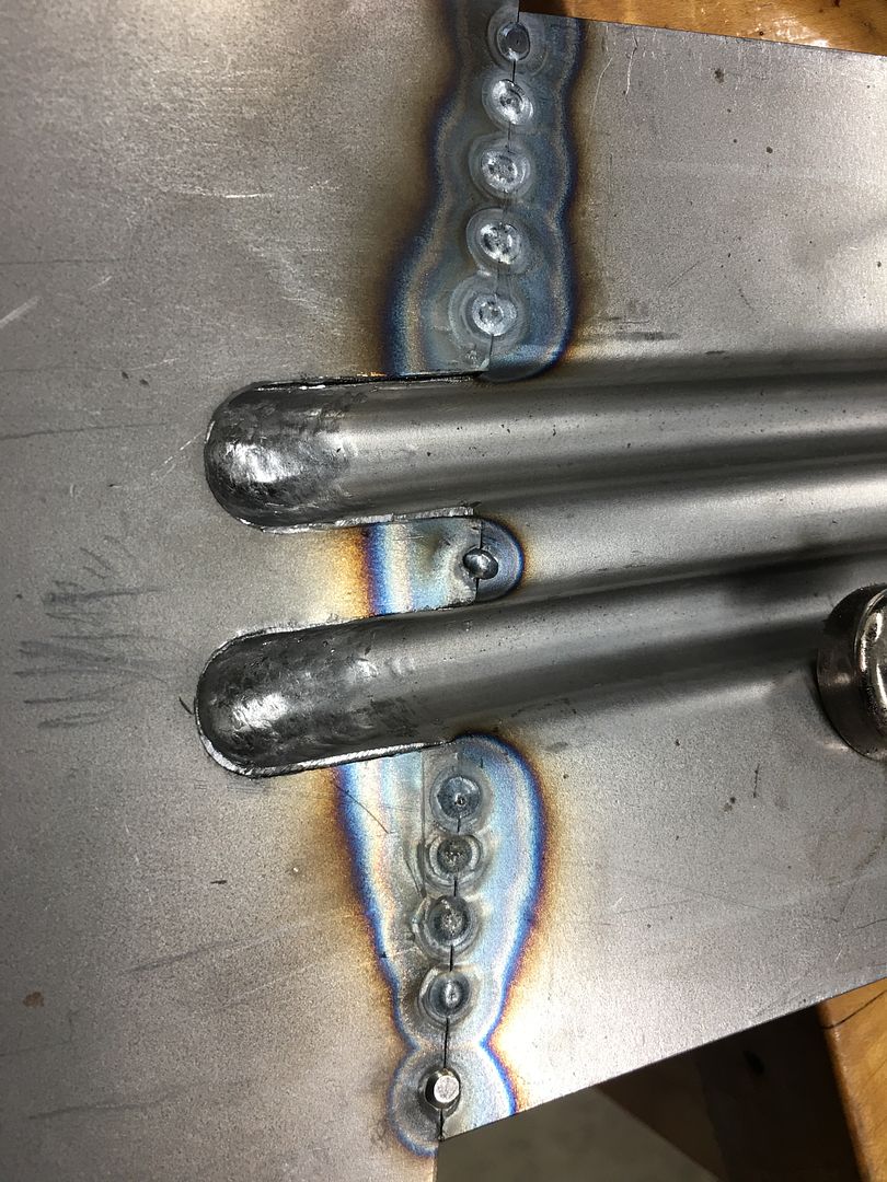
Now that tacks are done from one end to the other, planish while the dots are all by their un-obstructed individual lonesome self. This will give you a stretch that pushes outward in all directions, opposite of what happened with the shrinking as it cooled. By doing the single task of planishing from one end to the other we can also keep our planishing efforts (amount of swing) more consistent from one weld dot to the next. Then check with profile template to see if the panel is still "out" where it should be. This should tell us if we had enough planishing effort. Planish again if needed to keep the panel in check. Now grind each weld in the same successive pattern, one end to the other, start to finish. FRONT AND BACKSIDE! You want the bulk of the weld proud out of the way of the next set of welds so we can 1) planish without striking any other "obstacles" 2) keeps thickness the same as parent metal so our welder heat setting and trigger pull duration can have the same effect from one end to the other. A weld dot and the proud on either side can be 4 to 5 times the thickness of the parent metal. I'd suggest that is a heat sink and will change how your welder settings affect the next weld otherwise. Does the grinding here need to be perfect? no. But get weld dots as close to panel surface as you can without hitting either side or parent metal. Final sanding can be done at end.
Next, many would tell you to go to center between dots and keep filling in until all touch. My suggestion is to go back to first weld dot that was ground down, and overlap about 1/3. Skip to the second, same overlap. repeat all the way across the panel. Then do the planishing step all the way across, then grinding all the way across BOTH SIDES. Using this overlap process I think you'll find when done you no longer have those missed spots you've been checking for with a light. Sample on a repair we did on a roof:

Is this a slow, monotonous process? Sure is. But the end goal is to have consistency in how each and every weld is done. From size, to heat, to duration of trigger pull, to planishing effort amount, to grinding.... It is all part of the welding process. By keeping every step of the process consistent from one end to the other, I think you'll have better luck keeping the panel from warping to far out of kilter. Working each process from one end to the other also means that by the time I'm done tacking, the start end is already cool for me to start planishing. No useless artificial cooling needed.
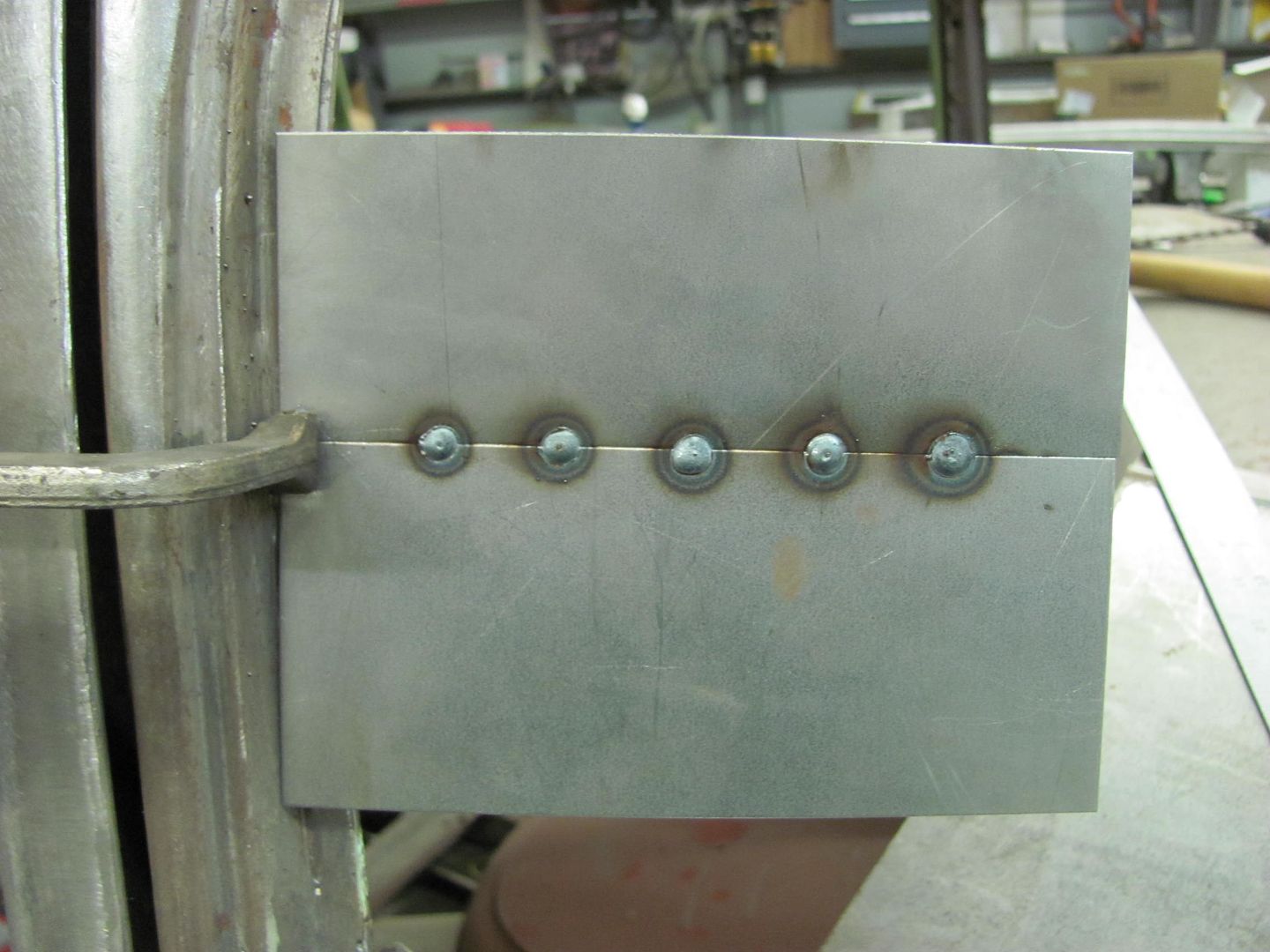
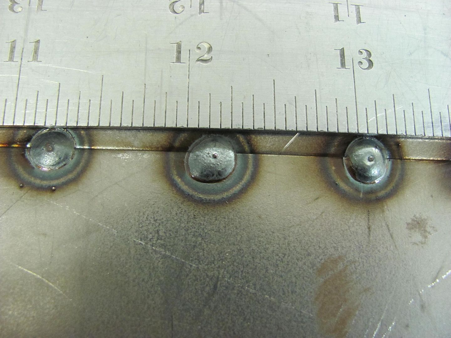
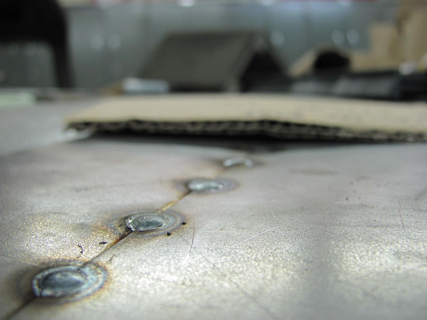
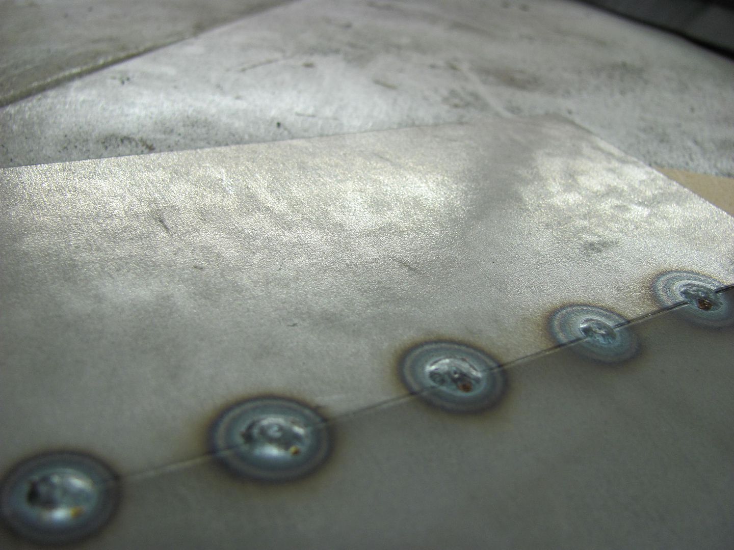
Side note, the nice FLAT welds in the picture above are possible because the heat is set hotter than the "machine's chart" recommended. The wire feed speed is bumped up slightly to prevent blowout, and the trigger pull duration is DECREASED. Note also the minimal HAZ surrounding the weld dots using this method..
Thread Starter
|
Tuned
Joined: Aug 2007
Posts: 459
Likes: 123
From: Maryland
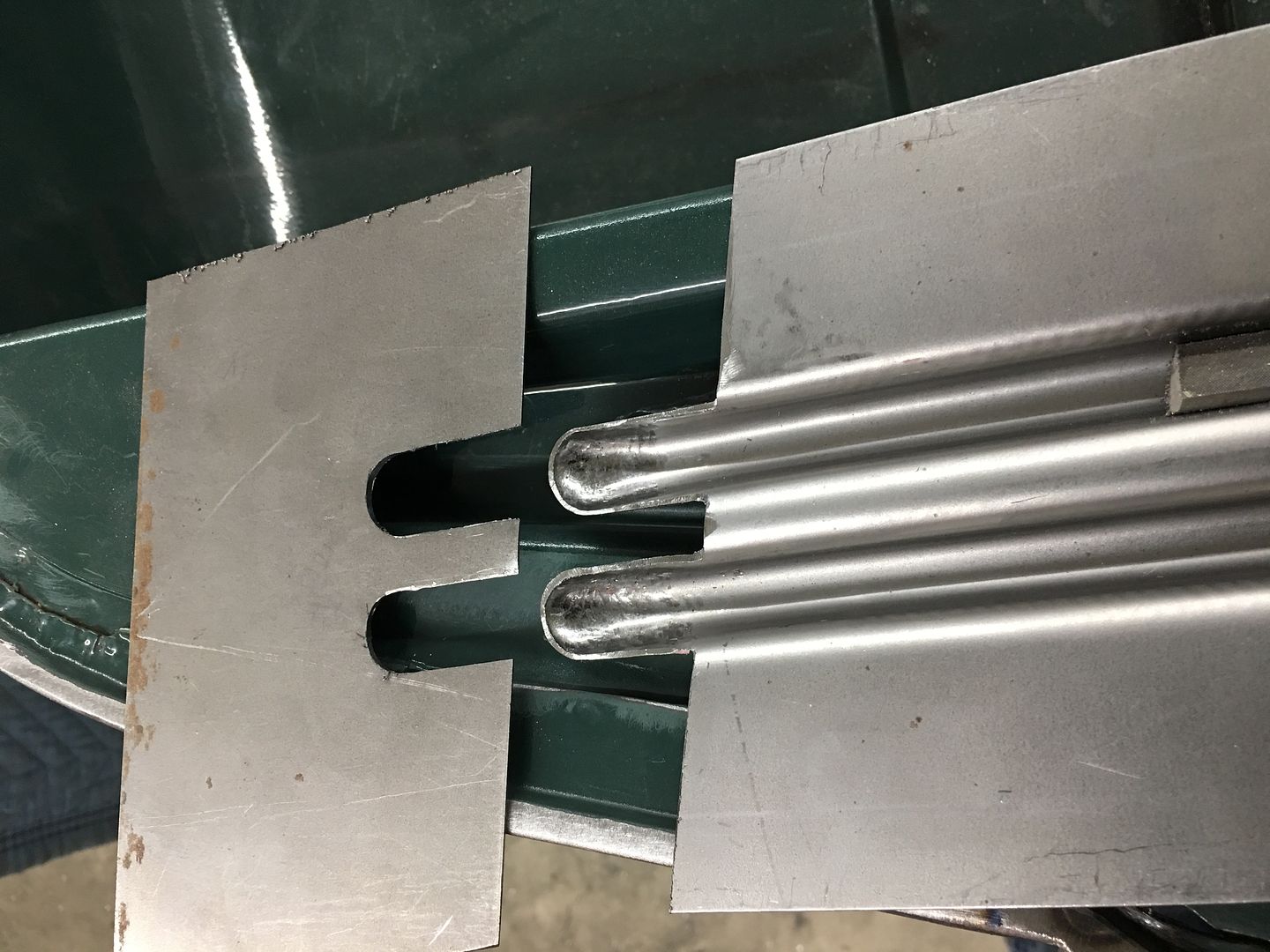
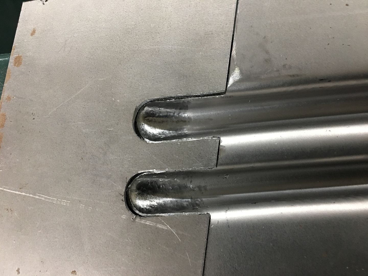
For initial set up on a MIG, I look first and foremost for FULL WELD PENETRATION while using a tight fitting butt weld. Anyone can fill a gap, but is it truly fused together properly? If you have weld proud on both front and back side of a tight fitting joint, you have a weld that has taken place. We aren't using a caulking gun here. Next, in the case you do have too much heat as evidenced by a blowout, realize that the one thing you DO have is full weld penetration. The panel is "blowing out" because there is not enough filler wire going in for said amount of heat, hence the panel becomes the consumable wire. So before turning down the heat, add more wire feed speed until you no longer have blowout. Now you are where you can fine tune the settings but more importantly, fine tune the operator. Get out of your head that the heat control **** controls the heat that the panel sees. If you can increase the heat, increase the feed speed, and decrease the elapsed time of trigger pull, you will in essence have a full penetrating weld with less proud for less planishing needed, less grinding needed. More heat gives you a flatter weld.
The colder your weld, the more proud you have on the top side of the panel, the less penetration you have in the panel. Once you have a cold joint, grind it off. You can pile on another 1/2" of blob, it will never penetrate properly. Here's a good sample...keep piling it on, still no weld penetration. What's holding it once you grind that mess down? (not my work, found picture online)

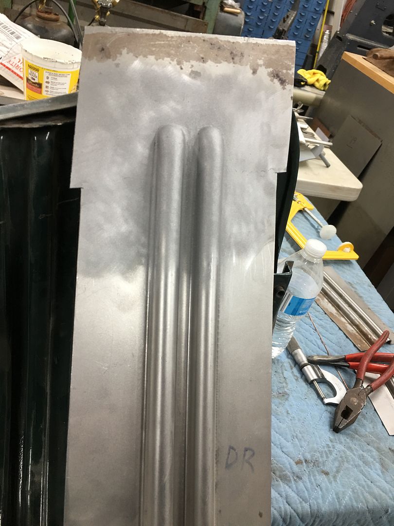
Side note..... you ran out of wire and just installed a new roll. Whether it's the same brand you used before or not, do some test samples if you are welding sheet metal. Always find out how everything works on a practice piece before jumping in on your good panels. Much of todays welding wire is made who knows where of who knows what. Get comfortable with it on scraps.. Also, note the pictures below show my test coupons in free air, just as your quarter panel on a car is. We don't do test coupons laying on a steel workbench because it is a heat sink and does not match the same conditions as the panels on your vehicle. Your practice should match those same conditions as your vehicle, so you are setting up the welder, fine tuning the settings, and fine tuning the operator...…all in the same conditions that exist on the vehicle... before you jump on your good panels
Here's some test samples that I did using more heat:
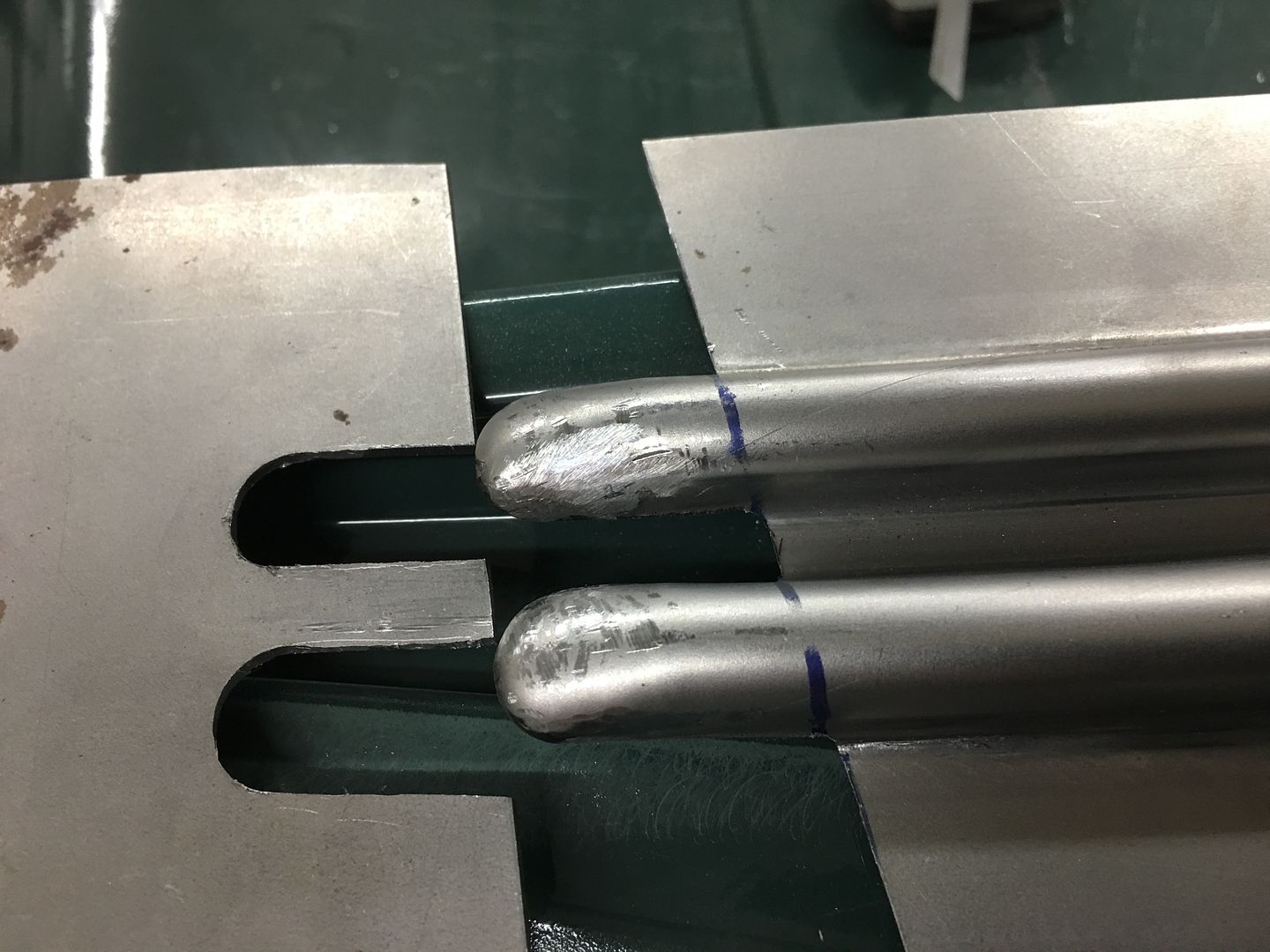
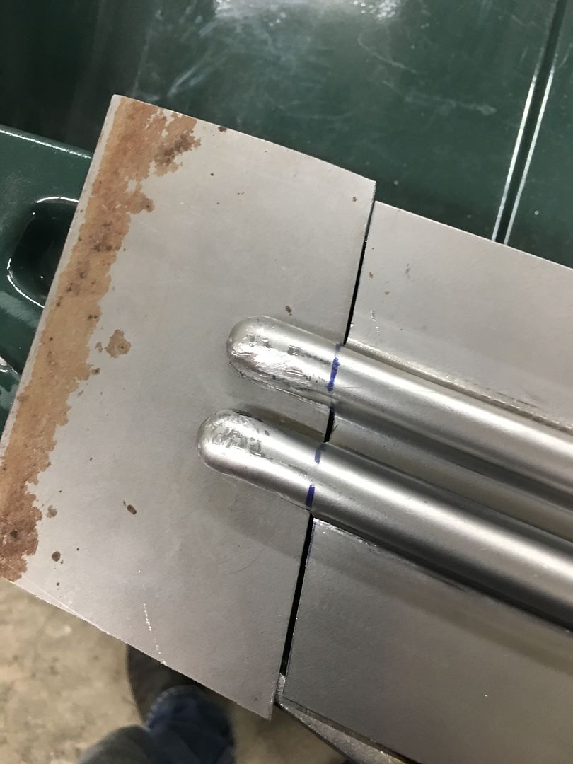
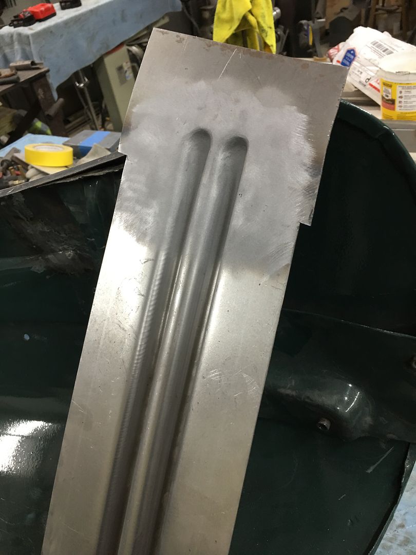
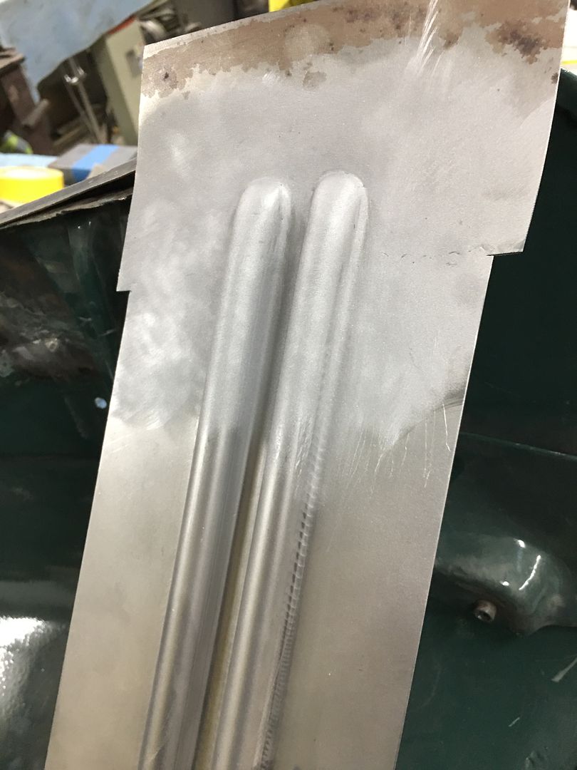
Installed .035 ER70S-7 in the machine, dialed in the settings for 3/16 thick steel, and ran some test welds... YES! HEAT SET FOR 3/16 STEEL!
Note the minimal HAZ for the size of the weld dot, note the minimal build in the side profile shots...………..
Front side....

Rear side....
The duration of trigger pull on these was less than a second, likely about 1/2 second. So the end goal of your practice should be welder setup, adjusting operator technique, and minimal proud/flatter welds having full penetration..
Note the minimal HAZ for the size of the weld dot, note the minimal build in the side profile shots...………..
Front side....
Rear side....
The duration of trigger pull on these was less than a second, likely about 1/2 second. So the end goal of your practice should be welder setup, adjusting operator technique, and minimal proud/flatter welds having full penetration..


