

38R Surge!

Postmaster
Joined: Jun 2006
Posts: 2,647
Likes: 0
From: Fulltime RVer

I finally got my computer fixed and then did some more thinking about "surge" and I came up with the picture below which might or might not be worth a thousand words?
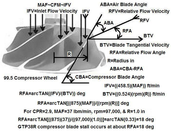
The bottom-line message above is that "surge" is caused by compressor blade "stall" and for a given compressor wheel rpm if the MAF which depends on engine RPM becomes too low the ABA=Air Blade Angle becomes too large and the compressor blades stall.
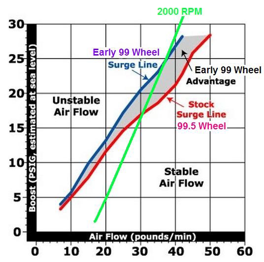
The configuration and blade angles of the compressor blades are the most important parameters for determining when surge occurs. The graph below compares the surge characteristics of the 99.5 wheel... http://ernesteugene.com/PSD/L99.5Wheel.jpg ...with the early 99 wheel... http://ernesteugene.com/PSD/E99Wheel3.jpg ...and with the early 99 wheel you can produce 7 psig more BP and 6 lbm/min more MAF at 2000 RPM before hitting the "surge line"!
If you compare a GTP38... http://ernesteugene.com/PSD/GTP38Pic.jpg ...with a GTP38R... http://ernesteugene.com/PSD/GTP38RPic.jpg ...the GTP38R has a larger diameter inlet with a "gap" around the perimeter of the compressor wheel and this gap allows the compressor blades to spin in a cleaner less disturbed airflow which probably helps to suppress the onset of stall somewhat and when stall does occur the "ported housing" allows a backflow of boost air into the gap region and this lessens the damaging effects of surging by limiting the variations in BP.
With a GTP38 the backflow of boost air is through the compressor housing inlet slot shown here... http://ernesteugene.com/PSD/TurboR.jpg ...and then back through the outer portions of the compressor blades and this disrupts the airflow there and causes a "hard stall" which in turn causes larger variations in BP that result in torque reversals during surging which damage the shaft bearings!
I used my 7.3L PSD computer model to analyze the performance of the three different A/R value GTP38R turbine housings listed here...
http://ernesteugene.com/FTE4/GTP38R_Table.jpg ...and I chose the operating point shown here... http://ernesteugene.com/PSD/Map1A.jpg ...which is just below the surge line with a compressor wheel rpm=93,000 which produces a BP=22 psig that in turn produces a MAF=35 lbm/min at 2000 RPM. Except for changing the stock GTP38 turbo to a GTP38R and changing the IMSV=Injector Maximum Stroke Volume mm^3/stroke from the stock 140 mm^3/stroke AD split-shot to a 160 mm^3/stroke AC single-shot everything else remains bone stock. Later I'll evaluate the effects of upgrading the air filter, IC, and tailpipe.
In all of the graphs that follow the "dotted-line" portion of a parameter curve refers to parameter values when the wastegate on the A/R=0.84 housing opens and bypasses various percentages of exhaust flow around the turbine. As indicated below when the VFF=Volume Fuel Flow gph reaches VFF=11 gph the A/R=0.84 wastegate begins to open so as to maintain the EBP at the correct value for keeping the BP at the constant value of BP=22 psig. For VFF values less than 11 gph the A/R=0.84 housing produces less than BP=22 psig and if its wastegate is properly positioned the A/R=0.84 housing maintains a constant BP=22 psig for higher values of VFF all the way up to VFF=21 gph. If the truck is on a load dyno the DRHP=Dyno Roller HP increases as the VFF increases so the correct load must be applied to the rear tires to maintain a steady 2000 RPM as more throttle is applied.
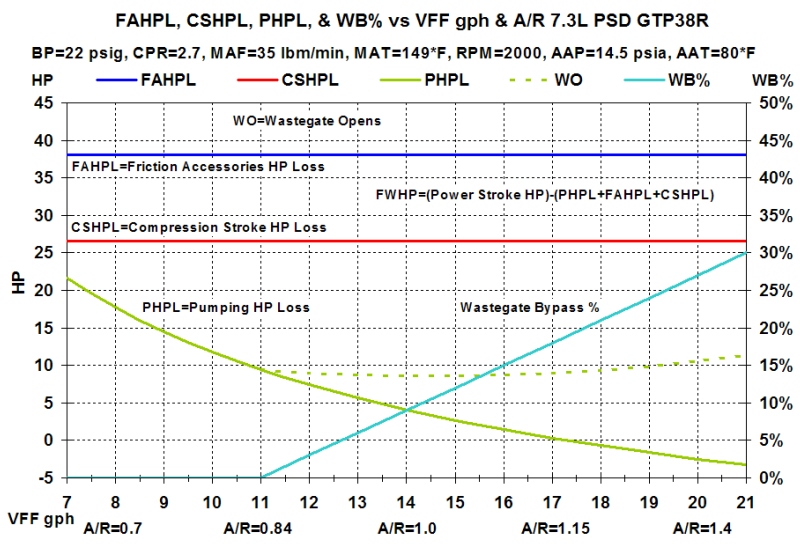
As indicated above the A/R=1.0 housing produces less than BP=22 psig until the VFF reaches a value of VFF=14 gph. Due to not wanting to clutter up the graphs I didn't plot the "dotted-line" portion of the parameter curves for the opening of the wastegate on the A/R=1.0 housing but for the PHPL=Pumping HP Loss curve above it would be a dotted line that's about 4.5 hp lower than the one shown for the A/R=0.84 housing. So the message so far is that the A/R=1.0 housing produces a BP=22 psig with 4.5 hp less PHPL which translates to 4.5 more FWHP but the A/R=0.84 housing produces a BP=22 psig with 3 gph less VFF.
The A/R=1.15 housing produces less than BP=22 psig until the VFF reaches a value of VFF=17 gph but when you finally do get a BP=22 psig the PHPL is only PHPL=0.3 hp which is 9.1 hp less than the PHPL needed to get BP=22 psig with the A/R=0.84 housing. Since the A/R=1.15 housing doesn't have a wastegate the BP increases above BP=22 psig when the VFF increases above VFF=17 gph and since the operating point being considered is just below the surge line a VFF not much higher than VFF=17 gph will surge the compressor when the A/R=1.15 housing is used! Well that's all for now! Below is the set of graphs and when I get time I'll do a write up on each of them.
http://ernesteugene.com/PSD/GTP38R_HPL.jpg
http://ernesteugene.com/PSD/GTP38R_FWHP.jpg
http://ernesteugene.com/PSD/GTP38R_IMSV.jpg
http://ernesteugene.com/PSD/GTP38R_EBP.jpg
http://ernesteugene.com/PSD/GTP38R_PSTE.jpg
http://ernesteugene.com/PSD/GTP38R_FWTE.jpg
http://ernesteugene.com/PSD/GTP38R_BSFC.jpg
The bottom-line message above is that "surge" is caused by compressor blade "stall" and for a given compressor wheel rpm if the MAF which depends on engine RPM becomes too low the ABA=Air Blade Angle becomes too large and the compressor blades stall.
The configuration and blade angles of the compressor blades are the most important parameters for determining when surge occurs. The graph below compares the surge characteristics of the 99.5 wheel... http://ernesteugene.com/PSD/L99.5Wheel.jpg ...with the early 99 wheel... http://ernesteugene.com/PSD/E99Wheel3.jpg ...and with the early 99 wheel you can produce 7 psig more BP and 6 lbm/min more MAF at 2000 RPM before hitting the "surge line"!
If you compare a GTP38... http://ernesteugene.com/PSD/GTP38Pic.jpg ...with a GTP38R... http://ernesteugene.com/PSD/GTP38RPic.jpg ...the GTP38R has a larger diameter inlet with a "gap" around the perimeter of the compressor wheel and this gap allows the compressor blades to spin in a cleaner less disturbed airflow which probably helps to suppress the onset of stall somewhat and when stall does occur the "ported housing" allows a backflow of boost air into the gap region and this lessens the damaging effects of surging by limiting the variations in BP.
With a GTP38 the backflow of boost air is through the compressor housing inlet slot shown here... http://ernesteugene.com/PSD/TurboR.jpg ...and then back through the outer portions of the compressor blades and this disrupts the airflow there and causes a "hard stall" which in turn causes larger variations in BP that result in torque reversals during surging which damage the shaft bearings!
I used my 7.3L PSD computer model to analyze the performance of the three different A/R value GTP38R turbine housings listed here...
http://ernesteugene.com/FTE4/GTP38R_Table.jpg ...and I chose the operating point shown here... http://ernesteugene.com/PSD/Map1A.jpg ...which is just below the surge line with a compressor wheel rpm=93,000 which produces a BP=22 psig that in turn produces a MAF=35 lbm/min at 2000 RPM. Except for changing the stock GTP38 turbo to a GTP38R and changing the IMSV=Injector Maximum Stroke Volume mm^3/stroke from the stock 140 mm^3/stroke AD split-shot to a 160 mm^3/stroke AC single-shot everything else remains bone stock. Later I'll evaluate the effects of upgrading the air filter, IC, and tailpipe.
In all of the graphs that follow the "dotted-line" portion of a parameter curve refers to parameter values when the wastegate on the A/R=0.84 housing opens and bypasses various percentages of exhaust flow around the turbine. As indicated below when the VFF=Volume Fuel Flow gph reaches VFF=11 gph the A/R=0.84 wastegate begins to open so as to maintain the EBP at the correct value for keeping the BP at the constant value of BP=22 psig. For VFF values less than 11 gph the A/R=0.84 housing produces less than BP=22 psig and if its wastegate is properly positioned the A/R=0.84 housing maintains a constant BP=22 psig for higher values of VFF all the way up to VFF=21 gph. If the truck is on a load dyno the DRHP=Dyno Roller HP increases as the VFF increases so the correct load must be applied to the rear tires to maintain a steady 2000 RPM as more throttle is applied.
As indicated above the A/R=1.0 housing produces less than BP=22 psig until the VFF reaches a value of VFF=14 gph. Due to not wanting to clutter up the graphs I didn't plot the "dotted-line" portion of the parameter curves for the opening of the wastegate on the A/R=1.0 housing but for the PHPL=Pumping HP Loss curve above it would be a dotted line that's about 4.5 hp lower than the one shown for the A/R=0.84 housing. So the message so far is that the A/R=1.0 housing produces a BP=22 psig with 4.5 hp less PHPL which translates to 4.5 more FWHP but the A/R=0.84 housing produces a BP=22 psig with 3 gph less VFF.
The A/R=1.15 housing produces less than BP=22 psig until the VFF reaches a value of VFF=17 gph but when you finally do get a BP=22 psig the PHPL is only PHPL=0.3 hp which is 9.1 hp less than the PHPL needed to get BP=22 psig with the A/R=0.84 housing. Since the A/R=1.15 housing doesn't have a wastegate the BP increases above BP=22 psig when the VFF increases above VFF=17 gph and since the operating point being considered is just below the surge line a VFF not much higher than VFF=17 gph will surge the compressor when the A/R=1.15 housing is used! Well that's all for now! Below is the set of graphs and when I get time I'll do a write up on each of them.
http://ernesteugene.com/PSD/GTP38R_HPL.jpg
http://ernesteugene.com/PSD/GTP38R_FWHP.jpg
http://ernesteugene.com/PSD/GTP38R_IMSV.jpg
http://ernesteugene.com/PSD/GTP38R_EBP.jpg
http://ernesteugene.com/PSD/GTP38R_PSTE.jpg
http://ernesteugene.com/PSD/GTP38R_FWTE.jpg
http://ernesteugene.com/PSD/GTP38R_BSFC.jpg
Postmaster
Joined: Jun 2006
Posts: 2,647
Likes: 0
From: Fulltime RVer
Since the FTE software obscures the bottom part of the x-axis on my graphs which gives the A/R values use the following guide to interpret the curves on my graphs. The "solid-line" portion of a parameter curve refers to the parameter values you'd get if you had a "variable geometry" turbine housing that continuously adjusted its A/R from A/R=0.7 at VFF=8 gph to A/R=1.4 at VFF=20 gph and if you had a VGT that went from A/R=0.7 at VFF=8 gph to A/R=0.84 at VFF=11 gph and then remained at A/R=0.84 for higher VFF but opened a wastegate to bypass 0% to 30% of the exhaust flow as the VFF increased from VFF=11 gph to VFF=21 gph you'd get the combined "solid-line" portion of a parameter curve followed by the "dotted-line" portion of the curve.
In some cases the graphs were too cluttered so I didn't include the "dotted-line" portion of a curve for the wastegated A/R=0.84 housing. Also note that all of the curves on all of the graphs are for a fixed operating point at BP=22 psig and RPM=2000 along with the other fixed conditions noted such as MAT=149*F, AAP=14.5 psia, and AAT=80*F all of which combine to give a fixed MAF=35 lbm/min.
Well if you look at the graph below surge would only be a concern if you operate with an EGT higher than about 1350*F which might happen briefly as you pass through 2000 RPM during a WOT acceleration but most won't intentionally tow up a long grade with an EGT=1350*F!
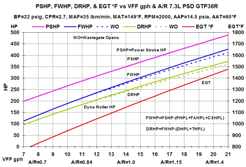
The "solid-line" portion of the above curves for FWHP and DRHP show that if the A/R=1.15 housing is used at a VFF=17 gph you'd get a FWHP=345.3 and a DRHP=301.7 but unless you've got very good vision and use a very large magnifying lens you'd actually need to be looking at my spreadsheet to get those exact values!
The "dotted-line" portion of the curves for FWHP and DRHP show that if the wastegated A/R=0.84 housing is used at a VFF=17 gph you'd get a FWHP=336.6 and a DRHP=294.1 so using the non-wastegated A/R=1.15 housing versus the wastegated A/R=0.84 housing gives a net gain of 8.7 FWHP and 7.6 DRHP which might be enough to help win a dyno contest but is a trivial increase in towing HP!
Also note that if you use the wastegated A/R=0.84 housing or the non-wastegated A/R=1.15 housing you get the exact same values of PSHP=410.2 and EGT=1291*F at VFF=17 gph but since there's 8.7 hp less PHPL with the A/R=1.15 housing it gives a net gain of 8.7 FWHP at the same EGT! When I get to the EBP versus BP graph I'll discuss how the A/R=1.15 housing gives the potential for "scavenging" which can result in additional gains in FWHP.
One day I'll do a detailed post to explain the basics of EGT and try to address some of the "common myths" about EGT but for now just consider that EGT depends the "heat content" of the intake air mass which is determined by the MAT, and on the "heat of compression" that's added during the compression stroke, and on the "combustion heat" that's added by combusting a given fuel mass with a given air mass, and on the "heat loss" to the coolant, and on the "heat loss" involved in generating a given PSHP during the expansion stroke, and that in the example I just gave none of these parameters change!
In some cases the graphs were too cluttered so I didn't include the "dotted-line" portion of a curve for the wastegated A/R=0.84 housing. Also note that all of the curves on all of the graphs are for a fixed operating point at BP=22 psig and RPM=2000 along with the other fixed conditions noted such as MAT=149*F, AAP=14.5 psia, and AAT=80*F all of which combine to give a fixed MAF=35 lbm/min.
...Since the A/R=1.15 housing doesn't have a wastegate the BP increases above BP=22 psig when the VFF increases above VFF=17 gph and since the operating point being considered is just below the surge line a VFF not much higher than VFF=17 gph will surge the compressor when the A/R=1.15 housing is used!...
The "solid-line" portion of the above curves for FWHP and DRHP show that if the A/R=1.15 housing is used at a VFF=17 gph you'd get a FWHP=345.3 and a DRHP=301.7 but unless you've got very good vision and use a very large magnifying lens you'd actually need to be looking at my spreadsheet to get those exact values!
The "dotted-line" portion of the curves for FWHP and DRHP show that if the wastegated A/R=0.84 housing is used at a VFF=17 gph you'd get a FWHP=336.6 and a DRHP=294.1 so using the non-wastegated A/R=1.15 housing versus the wastegated A/R=0.84 housing gives a net gain of 8.7 FWHP and 7.6 DRHP which might be enough to help win a dyno contest but is a trivial increase in towing HP!
Also note that if you use the wastegated A/R=0.84 housing or the non-wastegated A/R=1.15 housing you get the exact same values of PSHP=410.2 and EGT=1291*F at VFF=17 gph but since there's 8.7 hp less PHPL with the A/R=1.15 housing it gives a net gain of 8.7 FWHP at the same EGT! When I get to the EBP versus BP graph I'll discuss how the A/R=1.15 housing gives the potential for "scavenging" which can result in additional gains in FWHP.
One day I'll do a detailed post to explain the basics of EGT and try to address some of the "common myths" about EGT but for now just consider that EGT depends the "heat content" of the intake air mass which is determined by the MAT, and on the "heat of compression" that's added during the compression stroke, and on the "combustion heat" that's added by combusting a given fuel mass with a given air mass, and on the "heat loss" to the coolant, and on the "heat loss" involved in generating a given PSHP during the expansion stroke, and that in the example I just gave none of these parameters change!
Postmaster
Joined: Jun 2006
Posts: 2,647
Likes: 0
From: Fulltime RVer
This EBP graph... http://ernesteugene.com/PSD/GTP38R_EBP.jpg ...is an updated version that gives three EBP curves. The "solid-line" blue EBP curve is for a "variable geometry" turbine housing that continuously adjusts its A/R value so as to provide the correct exhaust flow restriction that in turn produces the correct EBP value that's needed to work with the VFF dependent EGT value to produce a TSHP=51.1 hp which is the correct TSHP value needed to drive the compressor hard enough to generate the desired constant BP value of BP=22 psig.
The "dashed-line" lavender EBP curve is for a non-wastegated turbine housing with an A/R=0.84 or for a wastegated A/R=0.84 turbine housing with the wastegate tied closed and the "dotted-line" blue EBP curve is for a wastegated A/R=0.84 turbine housing where the wastegate begins to open at the EBP value that's needed to generate a BP=22 psig and then the wastegate opens the additional amount necessary for maintaining the correct EBP value that's needed to work with the EGT value to produce the TSHP=51.1 hp needed to generate a BP=22 psig.
I'll discuss more about this graph latter but for now think about the answers to these questions... (1) Does a higher restriction to exhaust flow cause a higher EGT? (2) Does closing the EBP warm-up valve far enough to cause an EBP=30 psig at 2000 RPM have the same effect on EGT as an A/R=0.84 exhaust turbine housing that causes an EBP=30 psig at 2000 RPM?

Senior User
Joined: Feb 2010
Posts: 383
Likes: 0
From: white pine,tn

I can get my hands on prob 3 van turbos one fursure. They are still on the engines. What all do i need to take of these engines with the turbo? I also have alot of turbo surge around 15psi, and around 1800-2000 rpms. I tow around 10500 to 13000 most of the time and i pull 4 days a week at least. Im going to do more mods to the truck got a 6.0 ic to put on the truck. What all should i do or get for the van turbo install or should i go with something else? Sorry for getting of the sub thanks for your time...

Thread
Thread Starter
Forum
Replies
Last Post
cabloom300
1999 - 2003 7.3L Power Stroke Diesel
8
May 23, 2017 12:04 PM
Surge08
Brakes, Steering, Suspension, Tires, & Wheels
4
Jan 15, 2011 11:39 PM


