


how to wire loop ammeter without a sender???


Post Fiend
Joined: May 2008
Posts: 7,641
Likes: 21
From: Poway, Ca.
i think i can sum this up,," truck wiring for dummys 2.0" as i didn't see this covered all that clearly in other posts... leave a nice LONG loop in the primary wire thats going to lay on the back of the gauge.. that way no matter if it's 6v pos ground or 12v neg ground,, you can get the gauge to read right just by reversing the direction of the wire running on the back side of the amp meter. if i remember the change from pos to neg ground always had the amp meter reading backwards unless you changed the direction of the wire on the back of the amp meter.
The main power wire doesn't "lay" on the back of the gauge. It runs through the loop attached to the back of the gauge. If you need to reverse it, you have to disconnect it and run it through the other direction anyway. Adding extra length to a main power wire that is 10 possibly 8 AWG is just going make a bigger pain out of managing that wire for absolutely no reason, and a loop close to the gauge will simply confuse the induction process. Wiring and guessing don't mix.
This is a 12 volt negative ground electrical system. Please see the quote below.
On a 12 volt negative ground system, the wire going through the loop should run in from the "B" post of the ignition switch,
into the loop from the discharge side of the gauge, and out of the loop on the charge side of the gauge, to the
starter solenoid post with the positive battery cable attached.
On the 6 volt positive ground system, the wire running through the loop should come from the "BATT" post of the 15 amp circuit breaker,
into the loop from the charge side of the gauge and out of the loop on the discharge side of the gauge, to the starter
solenoid post with the negative battery cable attached.
Iwana....In the rewire guide I sent you, look on page 35 "Charging System" Steps 7 thru 27 (under "Power Distribution") give you the simple step by step instruction on how to run this wire. Just do it one step at a time.

Thread Starter
|
Fleet Mechanic


Joined: Feb 2009
Posts: 1,662
Likes: 36
From: Las Vegas NV

ju;ie did you send it via email or pm...i been reading another trhead https://www.ford-trucks.com/forums/9...-4.html....but i cant find the actual process
Thread Starter
|
Fleet Mechanic
Joined: Feb 2009
Posts: 1,662
Likes: 36
From: Las Vegas NV
ok folks so i took a flash light and i found a little fuse box in there.i am guessing its for the hot bus because all my lights and horn are connected to it,so its powered all the time...the ig switch that has the signals and other things doesnt have a fuse
Post Fiend
Joined: May 2008
Posts: 7,641
Likes: 21
From: Poway, Ca.
Now, where does the wire that supplies power to your fuse holder come from?
Also, the Rewire Guide was with the Power Point electrical diagrams I sent. It is the MS Word document that was also attached.
I'll check the list and resend it to you.
Edit Note: I can't sort out the real names on the e-mails with your FTE names So I'm not sure if you got the drawings or not. Can you send me another e-mail at babbiebuddie@***.net Sorry about the confusion.
Post Fiend
Joined: May 2008
Posts: 7,641
Likes: 21
From: Poway, Ca.
Here, I'll just copy it in.
Send me an e-mail anyway so I can resend it to you.
I send about 3 of those out a day so it's hard for me to keep track of who gets what:
Here's the wiring procedure for your charge and power distribution. If your fuse box is wired off your ignition switch we can do your gauge another way - just let me know:
From the rewire guide:
Charging System
7. Remove the 10 AWG red wire from the pack and strip ½ inch of insulation from one end of the wire. Twist the strands tight. Lightly solder the end and when cool place a yellow eye terminal connector on the end and crimp.
8. Remove the retainer nut from the red (“Batt”) post of your one wire alternator and install the eye terminal on the red wire on the stud. Install the nut and tighten. [Edit Note: with a generator or traditional alternator with an external regulator, this wire would attach to the "batt" terminal of the voltage regulator]
9. Run that wire along the engine valley then up the fire wall to the left firewall opening Install the fusible link per the manufacturers instructions outside the firewall on this red wire then continue it through the opening in the firewall and run the wire down to the connecting lug of the HOT BUS.[fuse block]
10. Cut the wire with 2 extra inches, strip ½ inch of insulation, twist and solder the end of that wire.
11. Install the soldered end of the red wire into the mounting lug – do not tighten it. Take the red wire remaining and make a jumper wire long enough to run between the wire mounting lugs. Strip, twist and solder both ends of the wire and insert the ends into both mounting lugs.
12. Take the remaining red wire and strip, twist and solder one end. Insert the soldered end into the HOT BUS lug that has only the jumper wire in it (so each lug now holds two wires). Tighten both screws on the mounting lugs.
13. Run the remaining red wire up to the ignition switch. Do this so it runs up and across the firewall then straight out to the ignition switch position. Strip, twist, solder the end, and crimp on a yellow eye terminal connector.
14. Remove the nut from the “B” or “BATT” terminal of the ignition switch, and place the yellow eye terminal on it. Do not install the nut.
15. Strip, twist solder and crimp a yellow eye connector onto the remainder of the wire.
16. Place the yellow eye connector on the “B” or “BATT” terminal of the ignition switch and secure both with the nut.
17. Run that red wire back along the track and next to the original red wire going to the ignition switch back to the firewall and across to behind the instrument panel.
18. Run the red wire through the induction loop of the ammeter from the discharge side through to the charge side of the gauge.
19. Run that red wire neatly back to the firewall along the same path and next to the red wire originally going to the gauge. Then run it along the firewall to the right side firewall opening.
20 Run the Red wire through the firewall opening and neatly run it down to the large “B” or “Batt” post of the starter solenoid. Strip, twist, solder and crimp a large ring yellow eye terminal on the wire.
21. Remove the nut from and place the positive battery cable on the “B” or “Batt” post of the starter solenoid.
22. Place the large eye terminal of the red wire on the “B” or “Batt” post of the starter solenoid over the battery cable eye, and secure both in place with the nut.
23. Return any unused red wire to it’s package.
Power Distribution.
Note: At his point you get the “strip, twist, solder and crimp routine. You will do this at every connection using the appropriate size connector – Yellow for 10-12 AWG, Blue for 14-16 AWG, and Red for 18-22 AWG.
24. Un package the 10 AWG Orange wire, place an eye terminal connector on the end and connect it to the “A” or “ACC” stud of the ignition switch. Tighten it in place with the retaining nut.
25. Run the orange wire down along the same path and next to the two large red wires coming from the ignition switch to the mounting lug of the “SWITCHED BUS.”
26. Solder the wire end and insert it into the mounting lug of the “SWITCHED BUS”
26. Make an orange jumper wire the same as we did with the red wire on the “HOT BUS” and insert it into both mounting lugs of the “SWITCHED BUS.”
27. Tighten both lug screws on the mounting lugs of the “SWITCHED BUS.” Place the remaining Orange wire back in the package.
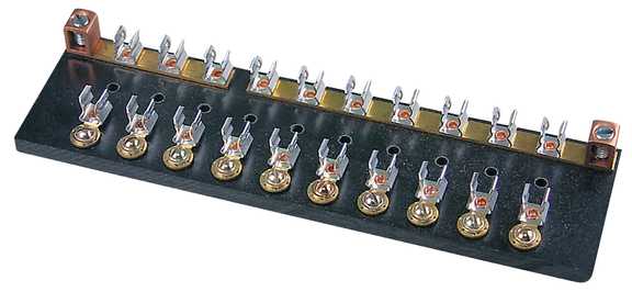
This is the fuse holder or "BUS" described in the procedure - note input lugs on both ends:
Send me an e-mail anyway so I can resend it to you.
I send about 3 of those out a day so it's hard for me to keep track of who gets what:
Here's the wiring procedure for your charge and power distribution. If your fuse box is wired off your ignition switch we can do your gauge another way - just let me know:
From the rewire guide:
Charging System
7. Remove the 10 AWG red wire from the pack and strip ½ inch of insulation from one end of the wire. Twist the strands tight. Lightly solder the end and when cool place a yellow eye terminal connector on the end and crimp.
8. Remove the retainer nut from the red (“Batt”) post of your one wire alternator and install the eye terminal on the red wire on the stud. Install the nut and tighten. [Edit Note: with a generator or traditional alternator with an external regulator, this wire would attach to the "batt" terminal of the voltage regulator]
9. Run that wire along the engine valley then up the fire wall to the left firewall opening Install the fusible link per the manufacturers instructions outside the firewall on this red wire then continue it through the opening in the firewall and run the wire down to the connecting lug of the HOT BUS.[fuse block]
10. Cut the wire with 2 extra inches, strip ½ inch of insulation, twist and solder the end of that wire.
11. Install the soldered end of the red wire into the mounting lug – do not tighten it. Take the red wire remaining and make a jumper wire long enough to run between the wire mounting lugs. Strip, twist and solder both ends of the wire and insert the ends into both mounting lugs.
12. Take the remaining red wire and strip, twist and solder one end. Insert the soldered end into the HOT BUS lug that has only the jumper wire in it (so each lug now holds two wires). Tighten both screws on the mounting lugs.
13. Run the remaining red wire up to the ignition switch. Do this so it runs up and across the firewall then straight out to the ignition switch position. Strip, twist, solder the end, and crimp on a yellow eye terminal connector.
14. Remove the nut from the “B” or “BATT” terminal of the ignition switch, and place the yellow eye terminal on it. Do not install the nut.
15. Strip, twist solder and crimp a yellow eye connector onto the remainder of the wire.
16. Place the yellow eye connector on the “B” or “BATT” terminal of the ignition switch and secure both with the nut.
17. Run that red wire back along the track and next to the original red wire going to the ignition switch back to the firewall and across to behind the instrument panel.
18. Run the red wire through the induction loop of the ammeter from the discharge side through to the charge side of the gauge.
19. Run that red wire neatly back to the firewall along the same path and next to the red wire originally going to the gauge. Then run it along the firewall to the right side firewall opening.
20 Run the Red wire through the firewall opening and neatly run it down to the large “B” or “Batt” post of the starter solenoid. Strip, twist, solder and crimp a large ring yellow eye terminal on the wire.
21. Remove the nut from and place the positive battery cable on the “B” or “Batt” post of the starter solenoid.
22. Place the large eye terminal of the red wire on the “B” or “Batt” post of the starter solenoid over the battery cable eye, and secure both in place with the nut.
23. Return any unused red wire to it’s package.
Power Distribution.
Note: At his point you get the “strip, twist, solder and crimp routine. You will do this at every connection using the appropriate size connector – Yellow for 10-12 AWG, Blue for 14-16 AWG, and Red for 18-22 AWG.
24. Un package the 10 AWG Orange wire, place an eye terminal connector on the end and connect it to the “A” or “ACC” stud of the ignition switch. Tighten it in place with the retaining nut.
25. Run the orange wire down along the same path and next to the two large red wires coming from the ignition switch to the mounting lug of the “SWITCHED BUS.”
26. Solder the wire end and insert it into the mounting lug of the “SWITCHED BUS”
26. Make an orange jumper wire the same as we did with the red wire on the “HOT BUS” and insert it into both mounting lugs of the “SWITCHED BUS.”
27. Tighten both lug screws on the mounting lugs of the “SWITCHED BUS.” Place the remaining Orange wire back in the package.
This is the fuse holder or "BUS" described in the procedure - note input lugs on both ends:

Thread
Thread Starter
Forum
Replies
Last Post
mrpotatohead
1967 - 1972 F-100 & Larger F-Series Trucks
18
Dec 27, 2016 11:28 PM
Fixnstuff
Pre-Power Stroke Diesel (7.3L IDI & 6.9L)
1
Sep 26, 2016 09:56 PM


