


how to wire loop ammeter without a sender???
Thread Starter
|
Fleet Mechanic


Joined: Feb 2009
Posts: 1,662
Likes: 36
From: Las Vegas NV

how to wire loop ammeter without a sender???
hello guys so today i got my 2 mechanical gauges for oil and temp.and i am following instructions given me by Julie, thanks Julie!!and now i found out i dont have the sender for the batt gauge,it is a loop style one,,,and i used the voltage reducer on my gas gauge and it doesnt seem to work...where is the ground for the whole cluser or how are the cables wired on that too
Hotshot


Joined: Oct 2009
Posts: 16,175
Likes: 4,782
From: Burbank, WA
Your ammeter is inductive, just like a timing light lead. The wire just goes through the loop and the gauge does the rest. It's important to have the wire going the correct direction for the gauge to read accurately.
Hotshot
Joined: Oct 2009
Posts: 16,175
Likes: 4,782
From: Burbank, WA
No, it has to be in a loop. The ammeter reads current movement, or battery charge and discharge. The wiring diagram should show that wire and the two connections it must make to function correctly. Understand that if you're wiring the truck as 12V negative ground, it will be connected in the reverse of the original 6V positive ground.
Thread Starter
|
Fleet Mechanic
Joined: Feb 2009
Posts: 1,662
Likes: 36
From: Las Vegas NV
pics
sorry but i am a numnuts when comes to electrical work well and everything else but i can fig it out by looking at pic...this is all i have and i dont have the sender i would like to used this but idk if ishoud use more aftermarket gauges
Fleet Owner


Joined: Jul 2004
Posts: 27,294
Likes: 1,055
From: NM
There is NO physical connection -- the big wire from the voltage reg simply passes thru the middle of the loop, and goes on to its connection on the breakers, or whatever.
Trending Topics
Thread Starter
|
Fleet Mechanic
Joined: Feb 2009
Posts: 1,662
Likes: 36
From: Las Vegas NV
could i use the big wire from the voltag reg from another truck car etc...my truck didnt come with and senders cables etc
FTE Stories
Ford Trucks for Ford Truck Enthusiasts

10 Things Every Truck Owner NEEDS (2026 Edition)
Michael S. Palmer
Rezvani's Latest Post-Apocalyptic Monster Is a Ford F-150 Raptor Underneath
Verdad Gallardo
Top 10 Most Expensive Ford Trucks Ever Sold on Bring a Trailer
Joe Kucinski
2027 Ford Super Duty Buyer's Guide (Every Model, Engine, & Package)
Brett Foote
Top 10 Ford Truck Tragedies
Joe Kucinski
AEV FXL Super Duty - the Super Duty Raptor Ford Doesn't Make
Brett Foote
Lobo Vs Lobo: Proof the F-150 Lobo Should Be Even Lower!
Michael S. Palmer
Ford's 2001 Explorer Sportsman Concept Looks For a New Home
Verdad Gallardo
10 Best Ford Truck Engines We Miss the Most!
Joe Kucinski
Post Fiend
Joined: May 2008
Posts: 7,641
Likes: 21
From: Poway, Ca.
Don't reuse old wire - buy new - especially for a main power wire.
There's a couple of variables with how the wire flows.
If your truck has been converted to 12 volt, do you have fuse blocks that you are using to distribute power out to everything? If not you need to have them.
If it is still 6 volt Positive ground, then you can use the stock circuit breakers on the truck.
The reason this is important is because you want your gauge to show the DIRECTION of the power flow through that loop in the back.
You have power in two places: Your generator produces it, and your battery provides it.
Normally , the generator voltage is slightly higher (more electrical "pressure"). So for 12 volt (because of the fuse holders) power flows from the generator,
to the regulator, out the regulator "B" post, then to your fuse holder that powers the HOT items (stuff that's powered all the time - lights, etc)
This is a LARGE wire, 10AWG at least.
From that distribution point that wire continues to the "BATT" post on your ignition switch, the up and through that loop (not connected it just travels
through the loop, insulation and all) and out to the same post on your starter solenoid that you battery cable is connected to.
In this configuration, another wire comes off your "ACC" post of your ignition switch to power a second fuse holder with all the SWITCHED items on it
(stuff that only is powered when the ignition is on - radio etc)
This is also at least 10 AWG.
That way as long as the power is flowing from the generator, it powers everything and then flows on to charge the battery.
But if your generator fails, that makes the battery power everything and the power flows in backwards - and the gauge shows that change to
opposite flow direction.
On the 6 Volt system, power to the ignition switch flows off the "Batt" post of the 15 amp circuit breaker. That means none of your SWITCHED
items have circuit breaker protection.
That should be in the electrical diagrams I sent you - take a look.
But for the forum, I'll post them again. They are easier to follow than the written instructuions anyway.
The first one is for 12 volt negative ground wiring with fuse holders ("HOT BUS" & "SWITCHED BUS")
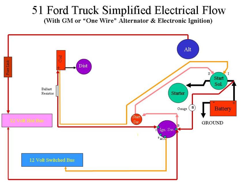
On a 12 volt negative ground system, the wire going through the loop should run in from the "B" post of the ignition switch,
into the loop from the discharge side of the gauge, and out of the loop on the charge side of the gauge, to the
starter solenoid post with the positive battery cable attached.
The second and third drawings are for the 6 volt OEM wire flow.
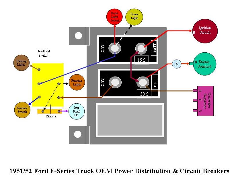
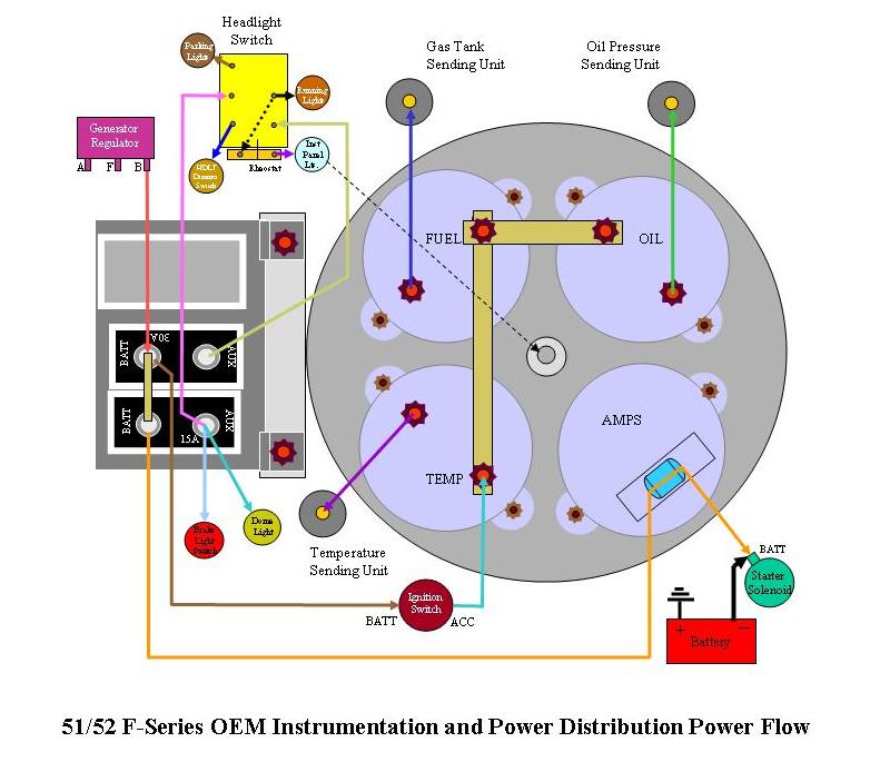
On the 6 volt positive ground system, the wire running through the loop should come from the "BATT" post of the 15 amp circuit breaker,
into the loop from the charge side of the gauge and out of the loop on the discharge side of the gauge, to the starter
solenoid post with the negative battery cable attached.
There's a couple of variables with how the wire flows.
If your truck has been converted to 12 volt, do you have fuse blocks that you are using to distribute power out to everything? If not you need to have them.
If it is still 6 volt Positive ground, then you can use the stock circuit breakers on the truck.
The reason this is important is because you want your gauge to show the DIRECTION of the power flow through that loop in the back.
You have power in two places: Your generator produces it, and your battery provides it.
Normally , the generator voltage is slightly higher (more electrical "pressure"). So for 12 volt (because of the fuse holders) power flows from the generator,
to the regulator, out the regulator "B" post, then to your fuse holder that powers the HOT items (stuff that's powered all the time - lights, etc)
This is a LARGE wire, 10AWG at least.
From that distribution point that wire continues to the "BATT" post on your ignition switch, the up and through that loop (not connected it just travels
through the loop, insulation and all) and out to the same post on your starter solenoid that you battery cable is connected to.
In this configuration, another wire comes off your "ACC" post of your ignition switch to power a second fuse holder with all the SWITCHED items on it
(stuff that only is powered when the ignition is on - radio etc)
This is also at least 10 AWG.
That way as long as the power is flowing from the generator, it powers everything and then flows on to charge the battery.
But if your generator fails, that makes the battery power everything and the power flows in backwards - and the gauge shows that change to
opposite flow direction.
On the 6 Volt system, power to the ignition switch flows off the "Batt" post of the 15 amp circuit breaker. That means none of your SWITCHED
items have circuit breaker protection.
That should be in the electrical diagrams I sent you - take a look.
But for the forum, I'll post them again. They are easier to follow than the written instructuions anyway.
The first one is for 12 volt negative ground wiring with fuse holders ("HOT BUS" & "SWITCHED BUS")
On a 12 volt negative ground system, the wire going through the loop should run in from the "B" post of the ignition switch,
into the loop from the discharge side of the gauge, and out of the loop on the charge side of the gauge, to the
starter solenoid post with the positive battery cable attached.
The second and third drawings are for the 6 volt OEM wire flow.
On the 6 volt positive ground system, the wire running through the loop should come from the "BATT" post of the 15 amp circuit breaker,
into the loop from the charge side of the gauge and out of the loop on the discharge side of the gauge, to the starter
solenoid post with the negative battery cable attached.
Thread Starter
|
Fleet Mechanic
Joined: Feb 2009
Posts: 1,662
Likes: 36
From: Las Vegas NV
it has been converted to 12 v and i dont have a fuse block so im gonna have to install one or easier to pay someone to do it for me,,,oooooor i could study electrical stuff for a month til i kind of understand....i guess there is no easy way thanks tho

Freshman User
Joined: Nov 2010
Posts: 25
Likes: 0
Your gauge works just like a amperage test meter. When a test meter is installed around a wire it will show the flow and how many amps. You can have fun and learn how your gauge works by taking a wire such as the one going to your head lights and pass it through the gauge. When the switch is off, the gauge will read neutral. When the lights are turned on, you will see the neeedle move one direction or the other. If the wire is going through it the wrong way, it will show it is charging. After you get use to how it works, route the wire between the alternator and the battery through it and it will show the direction of flow. If the motor is not running and you turn on some load such as head lights, the needle will show discharge. When the motor is running and it is sending juice to the battery, it will show charging.
Post Fiend
Joined: May 2008
Posts: 7,641
Likes: 21
From: Poway, Ca.
That's basically true - and I agree it's easy to see.
But in this case we don't know how he has distributed power - OIW where are all the wires are hooked up that run out to all the lights and stuff.
If the place they are hooked up (power distribution) is connected to the wire running from the alternator to battery on the wrong side of the gauge, then the gauge won't inticate at all when the lights are turned on because the power from the battery will flow out to the lights BEFORE it ever gets to the gauge.
There's a big picture kind of thing with this, and all this wiring has to be installed interactively/correctly for any of it to work right. You can't just cut it to bits and pieces, or singular circuits and think it will work.
Senior User
Joined: Oct 2010
Posts: 171
Likes: 0
From: Long Beach/Crestline, Ca
i think i can sum this up,," truck wiring for dummys 2.0" as i didn't see this covered all that clearly in other posts... leave a nice LONG loop in the primary wire thats going to lay on the back of the gauge.. that way no matter if it's 6v pos ground or 12v neg ground,, you can get the gauge to read right just by reversing the direction of the wire running on the back side of the amp meter. if i remember the change from pos to neg ground always had the amp meter reading backwards unless you changed the direction of the wire on the back of the amp meter.