


Rebuilding a BW1345

Thread Starter
|
Senior User
Joined: Jan 2003
Posts: 383
Likes: 1
From: Newport News USA
Rebuilding a BW1345
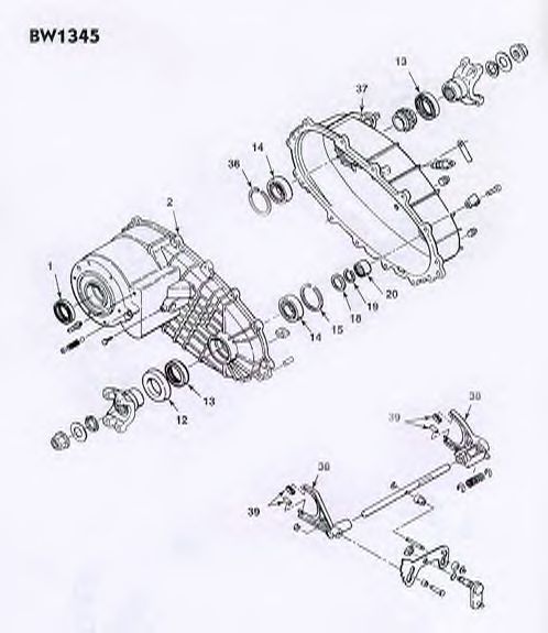
If you look at the picture, you'll see that the pins, pointed at with the red lines, go in the shaft with a spring in between 'em. Well, even without the spring they don't fit perfectly inside the shaft. They stick out about an 1/8 to 1/4 inch on each side. Well that's fine, as they're supposed to. They sit on top of the "oil pump" which is circled in blue. With the pump on the shaft, a portion of the pins sit on top and are what help create the flow of oil through the shafts and throughout that portion of the T-case. Yay!! Right now, with the shaft sticking through that plate in the diagram, and the pump on the shaft, the holes aren't uncovered enough to get the pins in. And since they are longer end-to-end than the diameter of the shaft, I can't slide the pump over them.
Anyone have a clue what the heck I'm talking about? Please oh please!!!
Once I figure this out, the rest should be fairly easy.
Thanks,
Luke

Fleet Mechanic

Joined: Nov 2003
Posts: 1,372
Likes: 14
From: West Cornwall, CT

The oil pump assembly on your 1345 transfer case looks just about identical to a 1356. Instructions for the 1356 follow.
Reassemble the pump and output shaft as follows.
a. Place the oil pump cover, with the word "top" facing the front of the case, on the output shaft.
b. Install two pins (with the flats facing the rear of the vehicle) with the spring between the pins in the oil pump bore in the output shaft.
c. Place the oil pump body and pick-up tube over the output shaft and make sure that the pins are riding against the inside of the pump body.
d. The word "top" on the front cover and the rear cover should be pointing in the same direction.
e. Install the pump retainer with the tabs facing the front of the transfer case.
f. Install the four retaining screws and rotate the output shaft while tightening the screws to prevent the pump from binding. Tighten the screws to 36-40 inch-pounds.
The output gear drive shaft must turn freely within the oil pump. If binding occurs, loosen the four screws and retighten.
Good luck!
Lou Braun
Thread Starter
|
Senior User
Joined: Jan 2003
Posts: 383
Likes: 1
From: Newport News USA
Thanks! I'll try that, and let ya know how well it works out. And I thought the only difference between the 1345 and the 1356 was the case? 1345 was all aluminum and the 1356 was a magnesium mix case. I'm sure there are other differences, I just don't know.
I appreciate the quick respons and help!
Luke
I appreciate the quick respons and help!
Luke

New User
Joined: May 2002
Posts: 20
Likes: 0
I noticed you had a picture/instructions. I am looking at rebuilding my BW1356 and was wondering if there anyone that has a set of pictures, insturctions of somekind that I could use to rebuild this thing. This will be my first X-fer case rebuild.. Most say to get a new one.. I would like to rebuild it just to know I can...
any help would be great
any help would be great
Thread Starter
|
Senior User
Joined: Jan 2003
Posts: 383
Likes: 1
From: Newport News USA
I just did a search for "borg warner 1356" on the web, and this should make you very happy!
http://www.wildercafe.com/fordtech/Thumbnails.asp
Good luck.
Luke
http://www.wildercafe.com/fordtech/Thumbnails.asp
Good luck.
Luke
New User
Joined: Oct 2003
Posts: 9
Likes: 0
From: norfolk
speedo drive gear
I am in the process of needing to change the speedo drive gear ( the one in the case) mine is worn out and making my speedo read incorrectly. My question is. Can I remove the gear by removing the rear output yoke and the rear output seal. And just pull it out from where the seal was are do I have to take the case apart to get to it. If I can do it through the rear, then is there a special tool needed to remove the seal.
This diagram shows I can but the one in the haynes shows it coming out by removing the case.
Any input is appreciated Thanks
lexluthr: Do you have a step by step to rebuild it are you just doing it on your own, does anyone noif there is a guide for the 1345
This diagram shows I can but the one in the haynes shows it coming out by removing the case.
Any input is appreciated Thanks
lexluthr: Do you have a step by step to rebuild it are you just doing it on your own, does anyone noif there is a guide for the 1345
Last edited by 85bigbronco; Jun 4, 2004 at 05:23 PM.
Thread Starter
|
Senior User
Joined: Jan 2003
Posts: 383
Likes: 1
From: Newport News USA
If I remember correctly, you 'should' be able to just pull the yoke off, then the seal and have access to it.
I just did it by feel and used the link I posted as a good reference even though it's for the 1356. They're so similar there is only minor differences in rebuilding each.
I just did it by feel and used the link I posted as a good reference even though it's for the 1356. They're so similar there is only minor differences in rebuilding each.
Trending Topics

Senior User
Joined: Aug 2003
Posts: 330
Likes: 0
From: clarks mills, PA
yes u can replace the gear withou splitting the case. get a new seal when you get the geaars because it will probably leak if you dont.
1. drop the front of the driveshaft
2. remove nut
3. remove yoke
4. remove seal (I just used a flat screw driver and a hamer)
5. remove speedo cable and sensor from top of case (not sure if its necessary but i already had mine out)
6. slide gear off of shaft
7. slide on the new one
8. reassemble in reverse
FTE Stories
Ford Trucks for Ford Truck Enthusiasts

Top 6 Best Deals Available on New Fords & Lincolns Right Now
Brett Foote
This Hennessey Takes the Expedition Tremor's Off-Roading Capability to the Next Level
Verdad Gallardo
Top 10 Fords at 2026 Carlisle Ford Nationals
Joe Kucinski
3 Best / 3 Worst Parts of Modern Ford Ownership
Brett Foote
10 Amazing Upgrades That Solve Common Ford Truck Owner Headaches
Pouria Savadkouei
Every 2026 Ford Engine Explained
Brett Foote
10 Ugly Ford Trucks That We Still Kinda Love
Joe Kucinski
10 Things Every Truck Owner NEEDS (2026 Edition)
Michael S. Palmer
Rezvani's Latest Post-Apocalyptic Monster Is a Ford F-150 Raptor Underneath
Verdad Gallardo

New User
Joined: Dec 2017
Posts: 9
Likes: 0
Sorry, long day at work. No, it�s the spring and plug that are installed AFTER the planetary gear set is installed. It provides the resistance and positive stops for shifting the case. I was afraid that driving the plug out would damage it, but it is indeed rather robust and comes out with a few healthy drives of a drift with a hammer. Be sure to use gasket sealer after you reinstall it and you will be fine.

Thread
Thread Starter
Forum
Replies
Last Post
TheSterling
1973 - 1979 F-100 & Larger F-Series Trucks
10
May 16, 2022 07:12 PM
sandymane
1987 - 1996 F150 & Larger F-Series Trucks
1
Jan 2, 2017 09:28 PM
Gary Lewis
1980 - 1986 Bullnose F100, F150 & Larger F-Series Trucks
123
Dec 4, 2016 08:10 AM
bsaastad
FE & FT Big Block V8 (332, 352, 360, 390, 406, 410, 427, 428)
15
Apr 18, 2016 07:38 AM