When you click on links to various merchants on this site and make a purchase, this can result in this site earning a commission. Affiliate programs and affiliations include, but are not limited to, the eBay Partner Network.
I have a 2004 Ford Econoline XLT, I have central power lock but no remote, wanted to add a simple cheap remote� I failed. i worked in the Kickerpanel (passenger side) using the brown and red wire + some hot wires and of course grounding. I couldn�t get it to work. When I connect the open/close signal to the qires and use the Remote I only get some sparks and the fuse blows. I just don�t understand it because when I don�t connect the wires and run the dry test I see all the correct voltage numbers. Do I need additional relays because Ford thought we can make this more difficult!? This should be so easy I did it on other cars but I burned the whole day and 10 fuses� There must be somebody who added a remote to a van to make life easier especially with the power lock system already functioning�
Your truck came with RKE? If so you just need a couple of the Ford keyfobs, set the system into programming mode and initialize the fobs.
Prepare Vehicle
CLOSE and UNLOCK vehicle using power door locks.
Enter Programming Mode
INSERT key into Ignition and TURN from OFF to RUN 8 times within 10 seconds, with the 8th time ending in RUN. Door locks will cycle to confirm Programming Mode.
Program Remote(s)
WITHIN 20 seconds PRESS ANY button on first keyless remote fob. Door locks will cycle LOCK/UNLOCK to confirm programming.
Program Additional Remote(s)
REPEAT the previous step IMMEDIATELY for any other remotes to be programmed to your vehicle.
Exit Programming Mode
TURN Ignition to OFF. Locks will again cycle to indicate end of programming mode.
Test Remote(s)
TEST all remotes. Programming is now complete.
no I don�t have the Factory Remote module in the van, I already tried that before.
I have successfully installed a fully functional PDL system on a 2000 E-250 not originally equipped with it as well and achieved remote actuation via an aftermarket car alarm. I've also used the same brand car alarm to trigger two different E-Series with RKE via the alarm system remotes, never have used the Ford remotes original to the van(s).
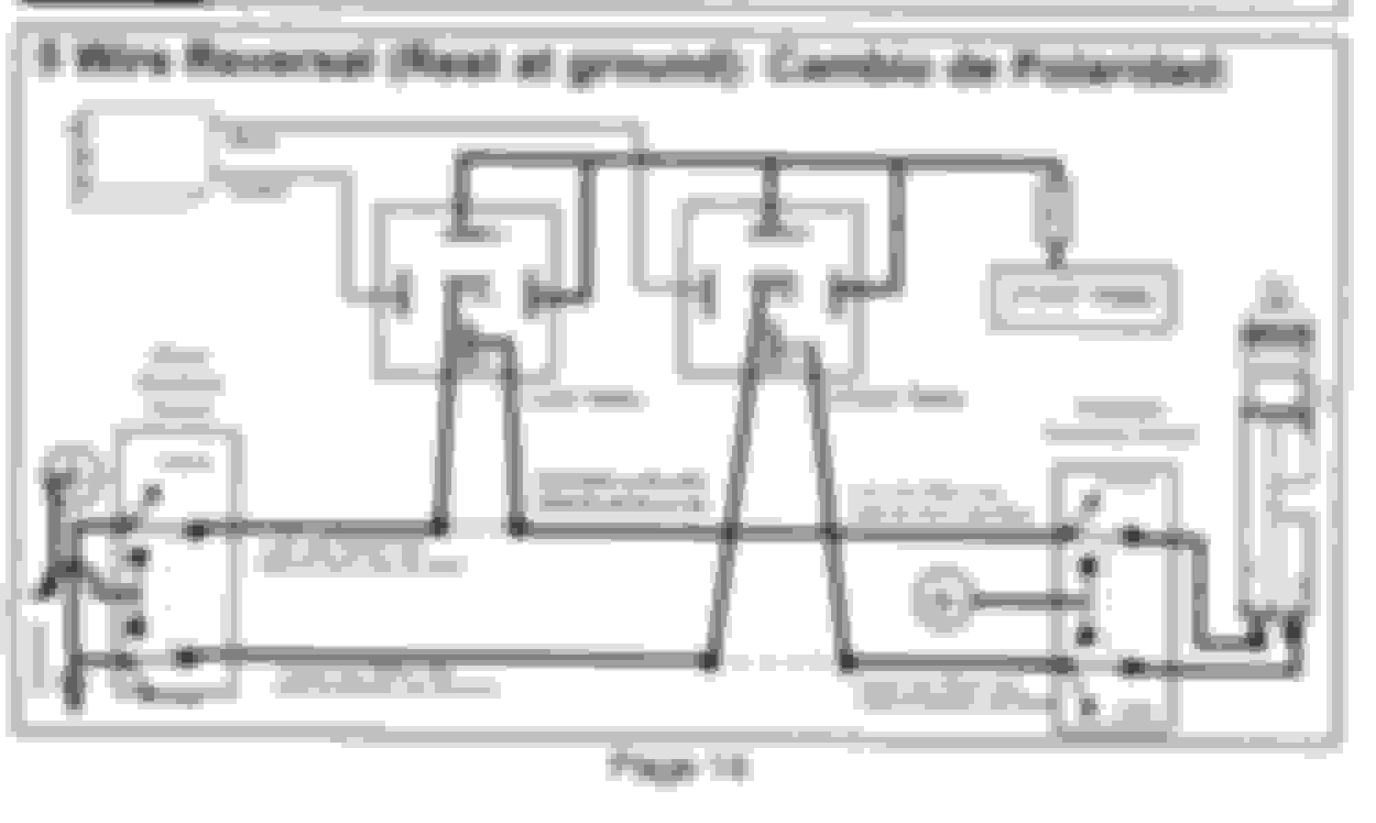
The key to this involves accessing the master control switch on the driver's door panel. You will have to fabricate a 5 Wire Reversal Rest At Ground circuit as shown here:
I would also suggest obtaining an EVTM or book of wiring diagrams for your year chassis which should be helpful integrating new DIY RKE system.
I have successfully installed a fully functional PDL system on a 2000 E-250 not originally equipped with it as well and achieved remote actuation via an aftermarket car alarm. I've also used the same brand car alarm to trigger two different E-Series with RKE via the alarm system remotes, never have used the Ford remotes original to the van(s).
The key to this involves accessing the master control switch on the driver's door panel. You will have to fabricate a 5 Wire Reversal Rest At Ground circuit as shown here:
I would also suggest obtaining an EVTM or book of wiring diagrams for your year chassis which should be helpful integrating new DIY RKE system.
That sounds all more complicated than I was hoping for, there is a wiring diagram that calls for a master switch. Can I do something with this? It involves the orange wires, but I have no idea where I have to connect these to on the car, sounds like I need to cut wires and but that module in between and not only parallel wire it.
The switch in the Passenger door has 6 wires.
constant ground (yellow red)
constant hot (black white)
Red (closing signal)
brown (open signal)
black (ground if switch not pushed)
black (ground if switch not pushed)
in the passenger kickpanel however it looks like there is only one black cable but an additional orange/red which is somehow connected to the switch in the door which I measured with an ohmmeter. When I push the button in the door, there is varies resistance between the black or orange/red wire and the closing/opening signal.
Why is this so complicated and not as easy as in every other Toyota Camry, Jeep, Chrysler,� etc.???
No doubt you�re smarter than me but you have to be smarter than a lot of other people. I struggled with this for a long time. Ultimately, when manufacturers provide such instructions and professionals execute those instructions, it�s the easiest and most cost effective solution. The series, reversing polarity and non-mechanical nature of the system is checkmate.
I�d pay $2-300 for a plug in module but no one sells one.
Sixto
07 E350 5.4 190K miles
check this guy out he sells a plug and play harness, that plugs in between.
I contacted him via Facebook, he sells it for 227 including shipping.
I just don�t want to spend so much, a local car radio guy quoted me 149 to put it in, I might go with that then.
What a bummer!
I recently installed an Avital 2101L keyless remote system into my 1997 E350. I bought the unit in ebay for about $40. The wiring is complicated and the Avital instructions are minimal and are written for industry pros. I found the youtue video listed above and copied the setup from the video. I got the connectors from a local self serve junkyard and built my own harness just like the video. I did not connect all of the parking lights to flash with the remote...only the left front turn signal. I used some Molex connectors but you can just splice the wires.
Here is a genereic diagram showing the door lock relays and how you have to interupt them with the keyless system SPDT relays.
Attached is my wiring diagram. The Avital unit is basically the SPDT relays shown in the diagram above. Don't get confused with the wire color changes. I had to extend some pigtail wires.
I really appreciate your information. I got it all installed and it works fine, the key was to install it �in row� instead of a parallel switch which I thought was the way to do it.
So basically the cheapest remote from Amazon/Ebay can be easy installed without any additional parts.
Last question would be if anybody knows where I can connect to the parking lights or flashers so I get a visual signal when I lock/unlock?
So I would not recommend to spend 227$ for the harness or even the $150, it was so easy I just did it wrong.
based on my diagram above I cut the red wire (closing) connected the orange wire to the red that comes out of the passenger door, the white to the red that goes in the car.
Then cut the brown and connect orange/black to the brown that comes from passenger door, white/black to the other brown end that goes in the car.
yellow and yellow/black and red goes on +12V and the black on -12V/car ground.
Glad you figured it out. As you noted the relays from the keyless module need to be in series with the LOCK signal and UNLOCK signal wires. This is what the wiring diagrams show in silghtly different formats. The nice thing about the Youtube kit is you don't have to cut and splice any wires and this may be a nice solution for those who are not excited about wiring.
There is no easy way to have all the turn signal/stop lights lights flash when the locks are cycled (you need to add diodes or isolation relays and splice a lot of wires). This is why the Youtube installation used the parking lights. I connected to the left front turn signal because it flashes brighter and I'm usually on that side of the van when locking the doors. The audible lock/unlock sound is loud enough to hear in most situations anyway.
I'm not sure where the parking and turn signals are located on an '05. My '97 has them on the headlight switch and column multi-function switch.
Rezvani's Latest Post-Apocalyptic Monster Is a Ford F-150 Raptor Underneath
Slideshow: Called the Fortress, the 850-horsepower pickup combines Raptor underpinnings with military-inspired features, survival equipment, and a starting price of $285,000.