When you click on links to various merchants on this site and make a purchase, this can result in this site earning a commission. Affiliate programs and affiliations include, but are not limited to, the eBay Partner Network.
I am trying to eliminate my radio and OH console from dimming when the headlights are turned on. Does anyone happen to know if one of the wires on the switch harness can be disconnected so the dimming function no longer activates? I tried the light blue wire with a red stripe and that disconnects the entire dash light circuit. My electrical is getting better, so that is good at least.
Your profile states you have a 1999, but your signature states you have a 2000. The wiring "should" be the same, but there are some differences in the wiring between the years. Most of those difference are for trucks that have a GEM vs. a VSM and the pinout map through the 42 pin connector over the driver side valve cover.
For the radio, looking at the Metra 70-1771 OEM harness adapter, orange is for illumination.
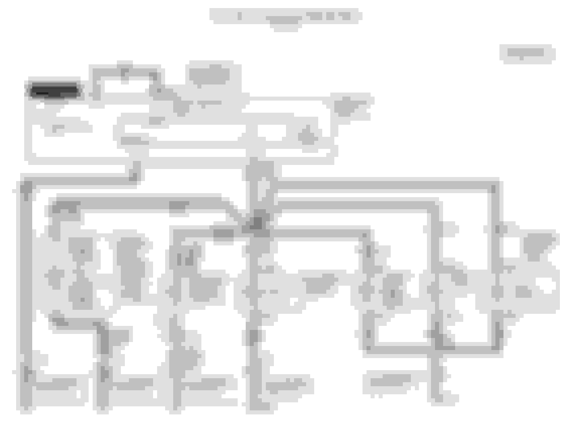
Although, this does not indicate a "dimmer" circuit in this very basic wiring diagram. The diagrams below are taken from the Ford Service Manual "connectors, components and diagrams" volumes.
Since you are well versed in reading wiring diagrams, I will not go into too much detail. You can see the multifunction switch (MFS) toward the top half which utilizes connector C230a.
Looking further into connector C230a below, you can see what the pinouts are based on the map/diagram.
Now that you know which circuits you may be looking at in order to remove the dimming function from the radio and OHU, we can look at the specific component information.
You can see the "radio" in the lower right corner of the diagram uses C257a and is on page 130-6.
Using the pinout map for C257a, you can verify what Metra told you above with what Ford tells you below and look for your circuit.
Just for reference and verification sake, I have included page 130-6 mentioned above.
Moving on to the overhead console module (OCM) as described by Ford.
You can see the OCM in the middle of the diagram below.
Looking at C911 which is for the OCM, the pinout map is below.
There is an entire section on "Instrument Illumination", but I have only included a couple of wiring diagrams for you to pick through, they are below.
The Pulse Width Dimmer Module (PWDM) noted above looks promising... Although, since you claimed to have already "tried the light blue wire with a red stripe" I can only assume you meant the LB/RD wire from the PWDM that follows "light blue with red trace" color code to both the OCM and the radio. Perhaps you will see something different based on your experience with reading wiring diagrams, but I am seeing that it is NOT possible to remove either of those circuits (radio and OCM) from the dimmer function simply by cutting a wire or removing a pin from a connector.
But...
There is hope...
Use a multimeter and test the voltage (v) being fed into pin 9 of the OCM and pin 1 of the radio.
Test the voltage at both connectors with the headlights off and then on with the truck in accessory.
Test the voltage at both connectors with the headlights off and then on with the truck in ON.
Test the voltage at both connectors with the headlights off and then on with the truck running.
Obviously take notes so that you don't have to remember each reading, at least that is what I do. I "suspect" the voltage reading at both pins will be ~12v with the headlights off and slightly lower with the headlights on, maybe ~9v. If this is the case, you may have found your solution and you already know this, but I will clarify for future readers.
You could tap into an "ignition/accessory on" circuit and plug that into pin 9 of the OCM and pin 1 of the radio. Be sure and cap/seal off the harness side of the wires you cut, or install new pins into the connectors and then cap/seal the pin off. Those wires/pins will still be hot when the truck is on.
The radio will be easy to tap into 12v ignition on because there is a 12v constant and a 12v accessory right there at the harness. I would suggest using this same circuit to run up to the OCM via dash, pillars and headliner, but that is up to you.
I hope this helps, if not, perhaps I can provide more advice, diagrams or pinout maps in order to clarify how you can achieve your goal of "eliminating" the dimming function from the OCM and radio.
I know from personal experience how much time it takes to prepare a post... looking up the relevant data... cross-referencing corroborating resources... verifying applicability for the purpose... converting the images from where found to a format that can be uploaded... reducing the size so that the screen doesn't blow back for cell phone readers... along with making suggestions on various courses of action that leverage the information you presented, as well as offering to follow through with continual help if needed.
I know from personal experience how much time it takes to prepare a post... looking up the relevant data... cross-referencing corroborating resources... verifying applicability for the purpose... converting the images from where found to a format that can be uploaded... reducing the size so that the screen doesn't blow back for cell phone readers... along with making suggestions on various courses of action that leverage the information you presented, as well as offering to follow through with continual help if needed.
Outstanding post!
Thank you for the compliment on the post, I appreciate it.
I only try to pay back this community in anyway I possibly can as it has done so much for me. Even if it takes hours to create a post with visual aids, diagrams, theories and ideas that is only a fraction of time that others have devoted to helping me in the past.
For future readers of this thread that may be having a hard time with the diagrams, I would like to reference a thread that FTE'r FordTruckNoob created a while back to help us all out.
In addition, for anyone that desires to use the Ford Service Manual in a way I and countless others do to help each other out, please see the link below.
I am trying to eliminate my radio and OH console from dimming when the headlights are turned on. Does anyone happen to know if one of the wires on the switch harness can be disconnected so the dimming function no longer activates? I tried the light blue wire with a red stripe and that disconnects the entire dash light circuit. My electrical is getting better, so that is good at least.
It would be far easier to just use some window tinting on the display screens. I used it on my A-pillar gauges, it works great, I can still easily see the display regardless of the time of day. The picture shows key on, lights off...
It would be far easier to just use some window tinting on the display screens. I used it on my A-pillar gauges, it works great, I can still easily see the display regardless of the time of day. The picture shows key on, lights off...
KISS
I think Byron is trying to keep his OH console and head unit displays bright, not make them dimmer.
I think Byron is trying to keep his OH console and head unit displays bright, not make them dimmer.
This is the way I read his request for help as well. Which, is why I stated hypothetical 9v and 12v readings from the radio and OCM.
He was not successful when he "tried" the LB/RD wire, so some measurements and investigating is in order, especially if he wants to keep the gremlins out.
I think Byron is trying to keep his OH console and head unit displays bright, not make them dimmer.
We had talked earlier in the day and I thought he was trying to dim them because he was looking for the wire responsible for it. He never went into details.
After taking a closer look at the diagrams @Sous posted, I think the LB/RD wire is the supply for illumination and not merely a signal. I think what @BBslider001 needs to do is disconnect the OH console's LB/RD wire and connect it to a "Hot in Run and Start" supply (for OH console illumination to be on whenever the truck is running) or a "Hot when parking lights are on" (for OH console illumination to be on whenever the parking lights are on). Then do the same for the head unit.
For the latter scenario, the wire to tap into is the BN wire coming from the Main Light Switch.
Leonard, that is what I was attempting to portray as well, but I would highly suggest voltage readings be taken during all conditions (6 of them) to ensure we know what we suspect.
Basically, we don't want to supply 12v to the OCM or radio if the full "brightness" supply voltage from the PWDM is 9v. I don't suspect this to be the case, but I am not a former electrical engineer for Ford.
Your thoughts on "Hot in Run and Start" is what I was getting at when I suggested the "ignition/accessory on" in post #2. The BK/VT (pin 10) on the radio harness is an easy source for that. He can tap pin cut pin 1 (LB/PK) and tap pin 1 into pin 10.
As long as the voltage measurements are correct.
For the OCM, same thing except pin 2 and pin 9 should be used. Again, as long as the voltage measurements are correct.
I initially thought the main multifunction switch was the primary target for removing the dimming feature, but then saw the PWDM in the diagram and the single illumination wire, which indicates to me the voltage changes based on what the PWDM is outputting as an illumination voltage.
If Colorado350 is correct, then KISS and use some tint. If not, then we may have figured out a solution for a request we haven't seen before in less than 24 hours.
One more thing, I didn't want to lead BBSlider001 on too much with what he should or shouldn't do, but wanted to offe options or ideas. This was the case because he has been doing A LOT of 12v wiring lately and possibly following wiring diagrams for RV converters, fridges, thermostats, etc.
I simply wanted to supply him the documentation from Ford so he could make an informed decision based on the information, details and facts provided. Sometimes wiring is simple, but sometimes it is very convoluted, especially when dealing with multifunction switch, modulation, varying voltages, splices, legs, branches...
Lions, tigers and bears oh my...
Electrical gremlins are attracted to this sort of thing, but planning, testing and confidence in action are the best way to mitigate or prevent a gremlin from having a death grip on your truck.
I think Byron is trying to keep his OH console and head unit displays bright, not make them dimmer.
Yes Leonard, this is exactly what I was wondering. Thanks for clarifying for me. With the not-so-new job now, I am constantly learning to be more specific when describing issues. I should have been more clear here.
Originally Posted by Colorado350
We had talked earlier in the day and I thought he was trying to dim them because he was looking for the wire responsible for it. He never went into details.
Sorry for the miscomm brother....see above response. Yes, it's just the digital readout in the OH and radio that goes dim when the lights are "on" that I wish I could mitigate.
Originally Posted by FordTruckNoob
After taking a closer look at the diagrams @Sous posted, I think the LB/RD wire is the supply for illumination and not merely a signal. I think what @BBslider001 needs to do is disconnect the OH console's LB/RD wire and connect it to a "Hot in Run and Start" supply (for OH console illumination to be on whenever the truck is running) or a "Hot when parking lights are on" (for OH console illumination to be on whenever the parking lights are on). Then do the same for the head unit.
For the latter scenario, the wire to tap into is the BN wire coming from the Main Light Switch.
Again, I appreciate all the input. Even though 12v wiring and AC wiring is becoming much more comfortable for me to diagnose and work with, I am not about to start splicing and cutting and redirecting wires in my truck, so to speak. I don't want those kinds of "ghetto" modifications to my stock system. My immediate supervisor is an absolute ninja with 12v and AC wiring. He also owns and drives a 2006 6.0 that he has modified himself and knows the nervous system of the Superduty ....what he said was there is no real way to accomplish what I am wanting unless I want to mess with the dimmer switch, direct wire to Hot/Start Supply, etc. I just said "say no more". It wasn't paramount enough to start that kind of rewiring. If it was cutting one wire, sure, but what we are talking here is going basically nuts for an issue that is not really an issue, but more of a want. I will say that when I tested the theory yesterday morning, I took out the headlight switch and actually removed the LB/Red Stripe wire from the harness....the correct way....and also put it back in and back together with no fear of setting something on fire LMAO A pick tool does wonders with small electronics. I have come a long way in 2 months. I am learning again, like anything else, you just have to do it and not be afraid to fail at it or mess something up.
Again, input is much appreciated. I learned something new with this.
Totally understandable. My wiring behind the driver kick panel is a rat's nest left behind by the PO that I'm still sorting out 12 years after buying the truck.
Totally understandable. My wiring behind the driver kick panel is a rat's nest left behind by the PO that I'm still sorting out 12 years after buying the truck.
Leonard, I have heard and read this story so many times. I don't understand why people mess with wiring and don't care when stuff does not work. My trailer wiring, you may remember, did not work properly due to the PO splicing, cutting, adding, subtracting, "making it better" or whatever. I bought a new factory harness, stripped everything down to the factory plug, plugged in the new harness, and trailer lights work beautifully. Why didn't the PO do this? No idea. What I had to cut out and redo was atrocious and idiotic. I pulled off THREE different plugs for trailers....and NONE of them worked properly. I wish that on no one.
My immediate supervisor is an absolute ninja with 12v and AC wiring. He also owns and drives a 2006 6.0 that he has modified himself and knows the nervous system of the Superduty
I do not doubt the advice from your immediate supervisor about his 6.0L, but I will tell you without a doubt, 1000% the wiring in the 2006 6.0 is dramatically different than the 7.3 you are driving and thinking through a project on. There are dramatic wiring differences between the 2000 and 2003 7.3L and they have the same IDM, injectors and major components, unlike the 6.0L compared to the 7.3L.
Originally Posted by BBslider001
what he said was there is no real way to accomplish what I am wanting unless I want to mess with the dimmer switch, direct wire to Hot/Start Supply, etc. I just said "say no more".
This is wrong... Think about it for a second... When you have the headlights OFF via the multifunction switch, what is the brightness of the radio and OCM? Now, turn the headlights ON via the multifunction switch. Did the radio and OCM dim? If the answer is yes, then ask yourself did you touch the dimmer rheostat (dimmer dial) or did you simply turn the multifunction switch from OFF to ON?
The "pulse width dimmer module" controls the voltage output, which sets the brightness on various accessories including the OCM and radio. The definition of a pulse width modulator is the following: Pulse width modulation is a great method of controlling the amount of power delivered to a load without dissipating any wasted power.
Again, I suspect at full brightness the voltage input to the radio and OCM is 12v and when the headlights are on the PWDM adjusts that voltage down to 9v or so based on the rheostat dial. If you had asked this question while I was working through my Android head unit project, I would have done the work for you and tested the PWDM voltage. Alas, my project is done and complete though so I do not plan to break into the wiring for a 5 second test with a DMM.
Originally Posted by BBslider001
It wasn't paramount enough to start that kind of rewiring.
No rewiring required since you have a 12v ignition on source of power at both locations for the radio and the OCM. A small splice with about 2" of wire at each location is most likely what is required.
Originally Posted by BBslider001
If it was cutting one wire, sure, but what we are talking here is going basically nuts for an issue that is not really an issue, but more of a want.
Well, it is two wires in total, but there is only one for each component (radio and OCM). You are right, one wire cut and spliced into another. Easy peasy... Use those fancy solder splice sleeves that Colorado350 recommended to you when you were installing a new pigtail on your UVCH a couple of weeks ago.
Originally Posted by BBslider001
I will say that when I tested the theory yesterday morning, I took out the headlight switch and actually removed the LB/Red Stripe wire from the harness....the correct way....and also put it back in and back together with no fear of setting something on fire LMAO A pick tool does wonders with small electronics. I have come a long way in 2 months. I am learning again, like anything else, you just have to do it and not be afraid to fail at it or mess something up.
Simple testing with a DMM would eliminate messing something up and proving you cannot fail as you would be testing the path forward, not guessing.
Originally Posted by BBslider001
Again, input is much appreciated. I learned something new with this.
Good to hear you learned something new as when we become stagnant in our ability to learn, life becomes stagnant. Your choice...
You had an idea, you asked for help here on the FTE, we provided you a clear path to success and if you want to abandon that idea due to lack of interest or not trusting wiring diagrams from Ford, that is up to you.
Hopefully your next idea will not be met with the same fate after Ford and the two brilliant FTE'rs (Y2KW57 and FordTruckNoob) above have shown you that it truly is attainable and for much less work than fixing your UVCH last week.
Rezvani's Latest Post-Apocalytic Monster Is a Ford F-150 Raptor Underneath
Slideshow: Called the Fortress, the 850-horsepower pickup combines Raptor underpinnings with military-inspired features, survival equipment, and a starting price of $285,000.


 ....what he said was there is no real way to accomplish what I am wanting unless I want to mess with the dimmer switch, direct wire to Hot/Start Supply, etc. I just said "say no more". It wasn't paramount enough to start that kind of rewiring. If it was cutting one wire, sure, but what we are talking here is going basically nuts for an issue that is not really an issue, but more of a want. I will say that when I tested the theory yesterday morning, I took out the headlight switch and actually removed the LB/Red Stripe wire from the harness....the correct way....and also put it back in and back together with no fear of setting something on fire LMAO A pick tool does wonders with small electronics. I have come a long way in 2 months. I am learning again, like anything else, you just have to do it and not be afraid to fail at it or mess something up.