


EO4D Complete Solenoid Pack Failure?

Thread Starter
|
Junior User
Joined: Jul 2017
Posts: 72
Likes: 0
EO4D Complete Solenoid Pack Failure?
I recently bought a ford f250 1992 7.5l and it started showing issues day one. I ran the codes and visted several forums from google searches. I pulled the harness plug and checked for exposed wiring and it seems to be in decent condition. My codes are 91,92,93,94 Engine off. These all translate to some solenoid circuit failure. My guess would be replace the pack, but before I go crazy replacing parts at random I thought I would see what others think. I find it very odd for all solenoids to be failing at one time.
Thread Starter
|
Junior User
Joined: Jul 2017
Posts: 72
Likes: 0
You'll have to excuse my ignorance when it comes to electrical knowledge. What I read from that was grab the solenoid female end of wire harness and use a ohm meter to detect resistance. Now when you say pin do you mean to stick the test prob to put red prob in 1 and black probe in 12. Then 1,2,3 etc and see if it reads 0 ohms?
Frmr Ford Trans Engr


Joined: Aug 1999
Posts: 24,739
Likes: 2,669
From: SE Florida
You'll have to excuse my ignorance when it comes to electrical knowledge. What I read from that was grab the solenoid female end of wire harness and use a ohm meter to detect resistance. Now when you say pin do you mean to stick the test prob to put red prob in 1 and black probe in 12. Then 1,2,3 etc and see if it reads 0 ohms?
Trending Topics
Fleet Owner


Joined: Aug 2005
Posts: 23,668
Likes: 301
From: Easton,Ks
The best way is to unplug the PCM Computer plug and plug the PCM harness connector into a Brake-Out-Box (BOB) and use your meter at the BOB.
BOB are nice for all kinds of tests on your OBD-1 trucks. You don't have to crawl under the truck to get to plugs and you do not have to stick pins in the wires. I have four OBD-1 trucks and it sure comes in handy for my trucks.
BOB are nice for all kinds of tests on your OBD-1 trucks. You don't have to crawl under the truck to get to plugs and you do not have to stick pins in the wires. I have four OBD-1 trucks and it sure comes in handy for my trucks.
FTE Stories
Ford Trucks for Ford Truck Enthusiasts

Top 6 Best Deals Available on New Fords & Lincolns Right Now
Brett Foote
This Hennessey Takes the Expedition Tremor's Off-Roading Capability to the Next Level
Verdad Gallardo
Top 10 Fords at 2026 Carlisle Ford Nationals
Joe Kucinski
3 Best / 3 Worst Parts of Modern Ford Ownership
Brett Foote
10 Amazing Upgrades That Solve Common Ford Truck Owner Headaches
Pouria Savadkouei
Every 2026 Ford Engine Explained
Brett Foote
10 Ugly Ford Trucks That We Still Kinda Love
Joe Kucinski
10 Things Every Truck Owner NEEDS (2026 Edition)
Michael S. Palmer
Rezvani's Latest Post-Apocalyptic Monster Is a Ford F-150 Raptor Underneath
Verdad Gallardo
Senior User
Joined: Oct 2016
Posts: 151
Likes: 1
You'll have to excuse my ignorance when it comes to electrical knowledge. What I read from that was grab the solenoid female end of wire harness and use a ohm meter to detect resistance. Now when you say pin do you mean to stick the test prob to put red prob in 1 and black probe in 12. Then 1,2,3 etc and see if it reads 0 ohms?
Fleet Owner
Joined: Aug 2005
Posts: 23,668
Likes: 301
From: Easton,Ks
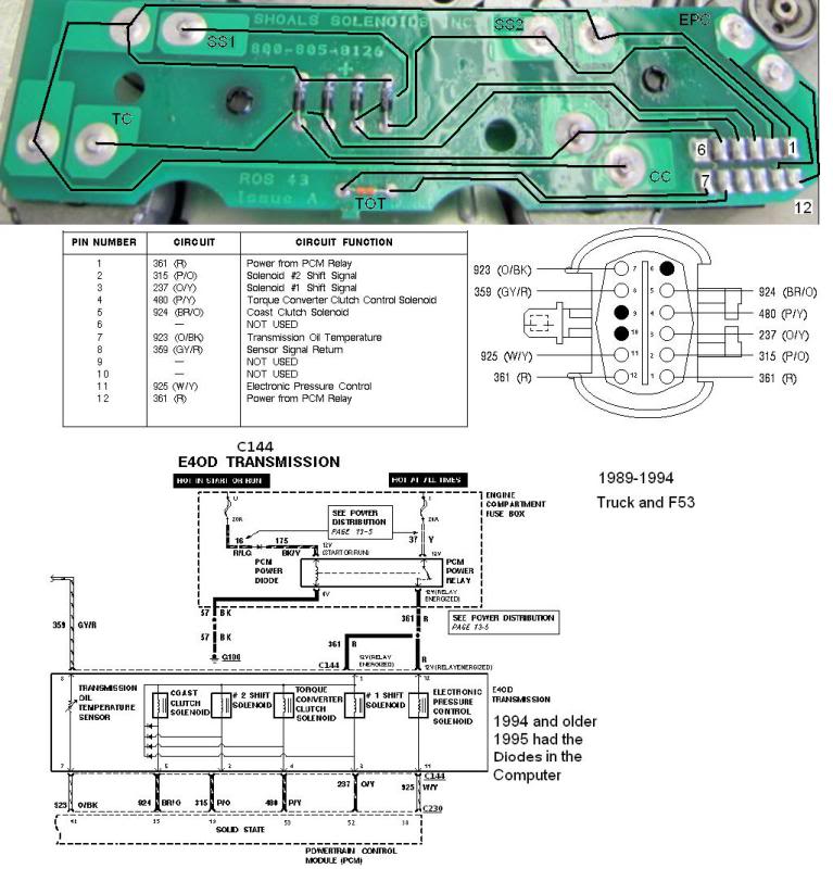
Image is for a 1995 and newer.
Wrong wire colors for wire 361 and its layout 1992-1994.
The pin out is right but pin 12 has the wrong wire color.
/
Wrong wire colors for wire 361 and its layout 1992-1994.
The pin out is right but pin 12 has the wrong wire color.
/
Last edited by subford; Jul 16, 2017 at 06:31 AM. Reason: Image removed for clarification
Thread Starter
|
Junior User
Joined: Jul 2017
Posts: 72
Likes: 0
I appreciate the help so far. I bought a multimeter this morning and have gone through all the fuses in both the cab and engine bay. I'll crawl under and check through the plug through the back vs the front.
Thread Starter
|
Junior User
Joined: Jul 2017
Posts: 72
Likes: 0
pin 1 and 12 should have 12v with the key on at the harness connector. Red lead on the meter to pin 1 and back lead to ground, then red lead to pin one black lead to ground. as Mark said dont jam the test lead into the pin, better to back probe it. If that checks out, then should measure the resistance of the solenoids at the pack itself or at the pcm. Best to get a wire diagram so you can get a better understanding of how it's laid out.

Thread Starter
|
Junior User
Joined: Jul 2017
Posts: 72
Likes: 0
Alright I bought some little pin probe tips for testing the connector. I also did some research on how to check for power 20v dc because we expect 12v from a healthy key on engine off connection. I also ebayed the 1992 shop manual and the 1992 electrical and vacuum manual for this F250. It seems to be hard to find complete drawings online so I assume buying those was my best bet. I checked both pins 1 and 12 at 20v dc on my multimeter with the red probe in and black probe grounded to the frame. Pin 1 (Red Wire) gave back a reading of 0 so I assume I have a power wire problem. Pin 12 (White, Red Stripe) came back at 12v. So that means either A my connector is bad in one pin or B there is a problem with the red wire up the line. What is the next step I should take? I traced the cable as I mentioned earlier, but it just webs off into several directions. Thank you.