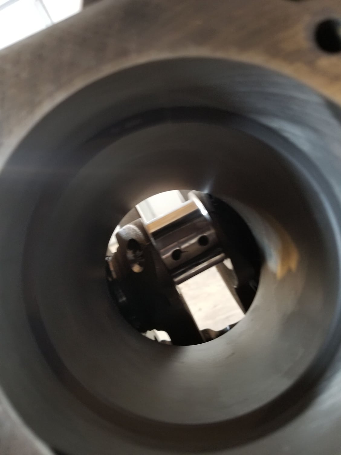
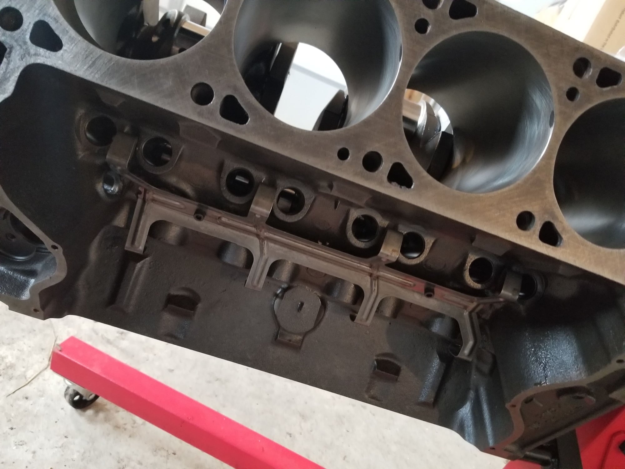
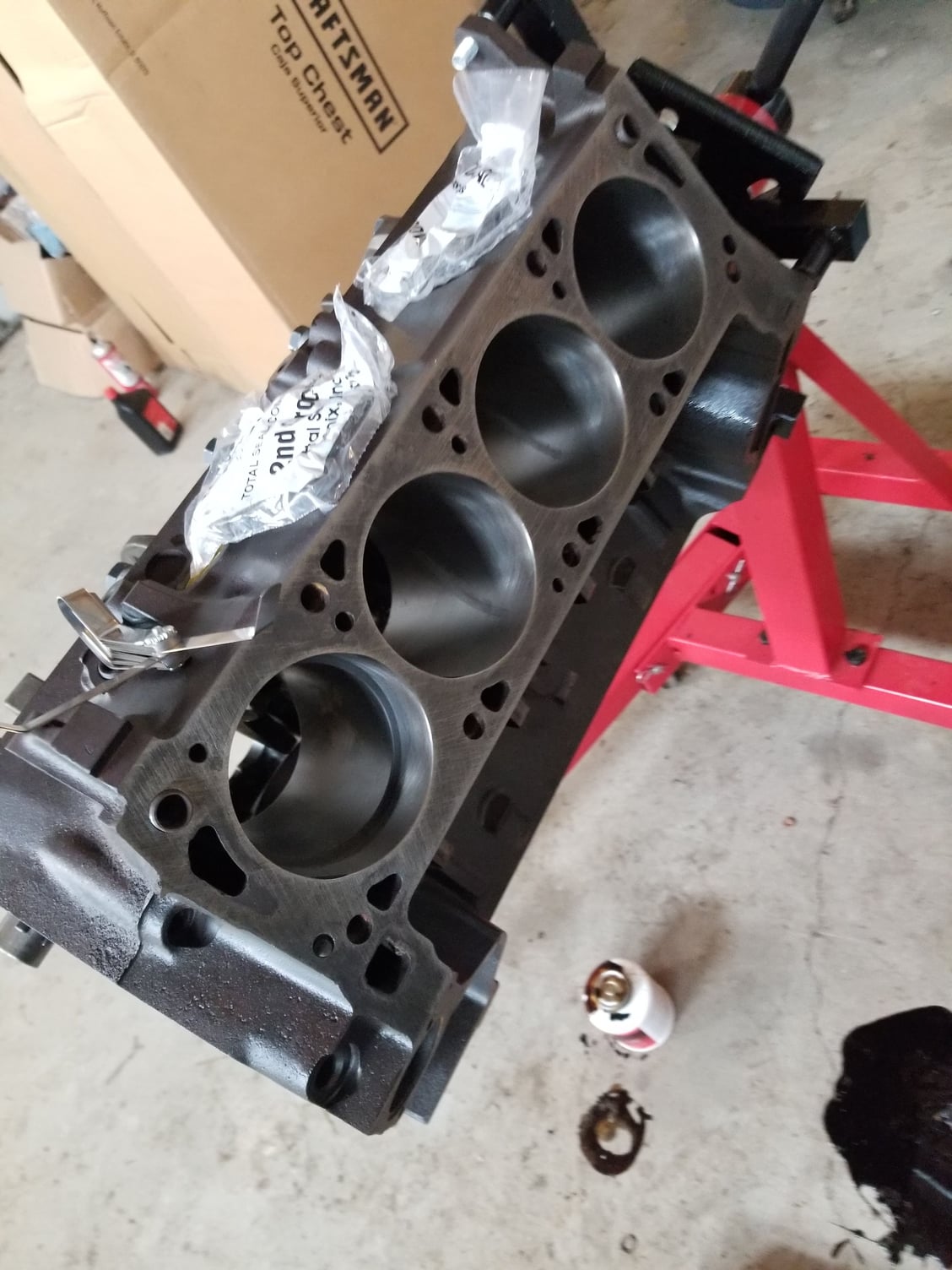
rebuild time
#32
sorry to resurrect the thread. but im finally to the point i can move forward with the engine. i had to get a new engine block. i dont trust the bore on the old one i pulled out of the pickup. im working with Tim on a kit. i found out i should go .040 over for pistons and i will need .020 bearings for main and rod bearings for this engine. im planning on getting this engine rebuilt with a roller cam and roller lifters along with tims pistons.
#34
we have it worked out. it will be a .040 over with tim's KB2347. i chose a comp cams hydraulic roller cam comp number #32-600-8 so duration is 283 intake 303 exhaust. and valve lift is at .557 intake and .539 exhaust. comp says "Thumpr™ : High performance street, stock converter ok, best with 2000+ converter and gears, choppy/thumping idle." the heads only have to have the valve spring area cut for a dual spring. the rod journals and main journals are .020 undersized. and i have an edelbrock performer and holley 1850 to go on top of the engine. this is going in front of a freshly rebuilt c6.
#35
I'm having a little struggle with figuring out ring gap. So the formula is bore x either .0045 or .0065 and I'm confused on which gap to go with because I'm getting different numbers. According to the total deal hand out it should be 4.04x.0045=.0018 ring gap for the first and second compression rings. Then other sights say to use 4.040x.0065=.0028 ring gap. I'm using total seal cr3690 40 ring to go with Tim's pistons.
or did I make a stupid mistake and these are ready to be installed onto the piston?
or did I make a stupid mistake and these are ready to be installed onto the piston?
#36
Join Date: Aug 2016
Location: Cape Town, South Africa
Posts: 723
Likes: 0
Received 2 Likes
on
2 Posts
There's several factors which determine the ring gaps.
Check with the rings supplier and/or Tim, and make sure you give them both the exact rings and pistons specs to be used.
They could well be 4.04'' x 0.0065'' top gap, and 4.04'' x 0.004'' second gap. Or vice versa !!
Having both the gaps the same does not sound right, but I could definitely be wrong.
My money's on 0.026'' top and 0.016'' second for those KB pistons.
#37
There's several factors which determine the ring gaps.
Check with the rings supplier and/or Tim, and make sure you give them both the exact rings and pistons specs to be used.
They could well be 4.04'' x 0.0065'' top gap, and 4.04'' x 0.004'' second gap. Or vice versa !!
Having both the gaps the same does not sound right, but I could definitely be wrong.
My money's on 0.026'' top and 0.016'' second for those KB pistons.
Check with the rings supplier and/or Tim, and make sure you give them both the exact rings and pistons specs to be used.
They could well be 4.04'' x 0.0065'' top gap, and 4.04'' x 0.004'' second gap. Or vice versa !!
Having both the gaps the same does not sound right, but I could definitely be wrong.
My money's on 0.026'' top and 0.016'' second for those KB pistons.
#39


#40
I bought a kind of stupid question that I'm just not sure about, And if anyone can give me a hand just so I know what's going on it would be much appreciated, I'm using Tim's pistons with factory 400 crank and 400 rods and I was wondering if I really had to have the Top of the cylinders decked to get the pistons to come up to flush or 0 deck?
#41
Join Date: Aug 2016
Location: Cape Town, South Africa
Posts: 723
Likes: 0
Received 2 Likes
on
2 Posts
That's a very good question. 
Yes and no.
If the deck is warped (E.G. higher one side than the other on the same block face), or if the pistons sit 10 miles down the bore, then yes, milling required.
If the deck has no warping, and the pistons are very close to zero deck (0.005'' say), then no milling required.
For you, I think check for warpage before you fit the pistons. (There's an allowable tolerance, but I can't remember what it is.)
Then after fitting the first piston, check the deck clearance. (Actually, check all 8 as you go along.)
Your's might actually be negative, say 0.005'' above the deck. (Not necessarily a problem.)
Seeing as the valve lift on that cam is 0.557'', give Tim your deck clearance figures (once obtained), tell him you're using his KB2347 pistons, and give him the valve lift figures.
Your question will then be, ''Will there be sufficient clearance between the piston face and valve''.
Please post up the answer to that question as I have no idea.
Talking about cams, you're gonna have some fun with that Chuck Norris cam !!
That block is nice 'n clean !
Did you have fun doing the ring gaps ?
It's the one job I didn't enjoy.
Make sure that the rings are the right way up (if marked) and that the gaps on each ring are 180 degrees opposite each other, or whatever the manufacturer states.

Yes and no.
If the deck is warped (E.G. higher one side than the other on the same block face), or if the pistons sit 10 miles down the bore, then yes, milling required.
If the deck has no warping, and the pistons are very close to zero deck (0.005'' say), then no milling required.
For you, I think check for warpage before you fit the pistons. (There's an allowable tolerance, but I can't remember what it is.)
Then after fitting the first piston, check the deck clearance. (Actually, check all 8 as you go along.)
Your's might actually be negative, say 0.005'' above the deck. (Not necessarily a problem.)
Seeing as the valve lift on that cam is 0.557'', give Tim your deck clearance figures (once obtained), tell him you're using his KB2347 pistons, and give him the valve lift figures.
Your question will then be, ''Will there be sufficient clearance between the piston face and valve''.
Please post up the answer to that question as I have no idea.
Talking about cams, you're gonna have some fun with that Chuck Norris cam !!

That block is nice 'n clean !
Did you have fun doing the ring gaps ?
It's the one job I didn't enjoy.
Make sure that the rings are the right way up (if marked) and that the gaps on each ring are 180 degrees opposite each other, or whatever the manufacturer states.
#42
That's a very good question. 
Yes and no.
If the deck is warped (E.G. higher one side than the other on the same block face), or if the pistons sit 10 miles down the bore, then yes, milling required.
If the deck has no warping, and the pistons are very close to zero deck (0.005'' say), then no milling required.
For you, I think check for warpage before you fit the pistons. (There's an allowable tolerance, but I can't remember what it is.)
Then after fitting the first piston, check the deck clearance. (Actually, check all 8 as you go along.)
Your's might actually be negative, say 0.005'' above the deck. (Not necessarily a problem.)
Seeing as the valve lift on that cam is 0.557'', give Tim your deck clearance figures (once obtained), tell him you're using his KB2347 pistons, and give him the valve lift figures.
Your question will then be, ''Will there be sufficient clearance between the piston face and valve''.
Please post up the answer to that question as I have no idea.
Talking about cams, you're gonna have some fun with that Chuck Norris cam !!
That block is nice 'n clean !
Did you have fun doing the ring gaps ?
It's the one job I didn't enjoy.
Make sure that the rings are the right way up (if marked) and that the gaps on each ring are 180 degrees opposite each other, or whatever the manufacturer states.

Yes and no.
If the deck is warped (E.G. higher one side than the other on the same block face), or if the pistons sit 10 miles down the bore, then yes, milling required.
If the deck has no warping, and the pistons are very close to zero deck (0.005'' say), then no milling required.
For you, I think check for warpage before you fit the pistons. (There's an allowable tolerance, but I can't remember what it is.)
Then after fitting the first piston, check the deck clearance. (Actually, check all 8 as you go along.)
Your's might actually be negative, say 0.005'' above the deck. (Not necessarily a problem.)
Seeing as the valve lift on that cam is 0.557'', give Tim your deck clearance figures (once obtained), tell him you're using his KB2347 pistons, and give him the valve lift figures.
Your question will then be, ''Will there be sufficient clearance between the piston face and valve''.
Please post up the answer to that question as I have no idea.
Talking about cams, you're gonna have some fun with that Chuck Norris cam !!

That block is nice 'n clean !
Did you have fun doing the ring gaps ?
It's the one job I didn't enjoy.
Make sure that the rings are the right way up (if marked) and that the gaps on each ring are 180 degrees opposite each other, or whatever the manufacturer states.
i will need to double check with tim but i think its something like .08 and .1 clearance between the valves and the piston. im not sure if the cylinders have been milled but ill have to get a straight edge and check as soon as i am able to!
Chuck Norris cam?! what do you mean?!?!
#43
Join Date: Aug 2016
Location: Cape Town, South Africa
Posts: 723
Likes: 0
Received 2 Likes
on
2 Posts
Yes, gapping the rings isn't difficult, but the fit, measure, remove, file, fit, repeat, repeat, repeat, is the bit I didn't enjoy. Time consuming as you said.
I've just read that your heads may be 0.03'' milled. If so, definitely give that fact to Tim as well.
And check if the valve train geometry will work and if the intake manifold will fit properly.
There is a way to check the valve clearances yourself, but if Tim has a database of info, that'll be much quicker !
The OE cam is a ''Driving Miss Daisy'' cam.
By comparison, looking at your cam specs, it will pack quite a punch, hence 'Chuck Norris cam''.

#44
Yes, gapping the rings isn't difficult, but the fit, measure, remove, file, fit, repeat, repeat, repeat, is the bit I didn't enjoy. Time consuming as you said.
I've just read that your heads may be 0.03'' milled. If so, definitely give that fact to Tim as well.
And check if the valve train geometry will work and if the intake manifold will fit properly.
There is a way to check the valve clearances yourself, but if Tim has a database of info, that'll be much quicker !
The OE cam is a ''Driving Miss Daisy'' cam.
By comparison, looking at your cam specs, it will pack quite a punch, hence 'Chuck Norris cam''.
I've just read that your heads may be 0.03'' milled. If so, definitely give that fact to Tim as well.
And check if the valve train geometry will work and if the intake manifold will fit properly.
There is a way to check the valve clearances yourself, but if Tim has a database of info, that'll be much quicker !
The OE cam is a ''Driving Miss Daisy'' cam.
By comparison, looking at your cam specs, it will pack quite a punch, hence 'Chuck Norris cam''.

if i did the math right i should be coming out with around 9.5-1 cr(give or take.15cr) with the timing chain straight up
#45


