


Alternator #2 code P1149, No start/long start.
Thread Starter
|
Senior User
Joined: Dec 2003
Posts: 330
Likes: 0
From: Newhall,CA
Alternator #2 code P1149, No start/long start.
Hey guys! It's been a long time since I've been on FTE, but it's good to be back!
The old man let me borrow his '06 F250 CC 4x4 with a 6.0 for my upcoming move. I have a bluetooth OBDII reader with Torque Pro and it started throwing this code at me:
P1149 ALT Generator 2 Control Circuit High Charging system
It ran fine until I turned it off to order food at Arby's, then it would just crank and not start. I towed it home last night and I jumpstarted it with my Jeep this morning after a long crank. I let it run for a good 45 mins to let it charge. Within about 15 minutes it started by itself twice, then I had to jump it again. Then I checked the voltage after jumping it:
Multimeter voltage:
Pass/Driver Batt idle: 13.4/13.2
Pass/Driver key off: 12.75/12.7 (after sitting 5 mins)
Driver key on, after glowplugs warm: 11.99
Again, no start, just cranking. It's got enough juice for the starter but not the injectors?
Is 13.4/13.2 lower than it should be? I know the Alternator probably needs replacing, but after hours of searching I've never seen anyone pull up P1149.
Which alternator is "generator 2?" Is it kosher to replace just one alt at a time if the other isn't pulling codes?
I suspect the bad alt is killing the batteries, sound about right?
Thread Starter
|
Senior User
Joined: Dec 2003
Posts: 330
Likes: 0
From: Newhall,CA
Is that ICP voltage? The pressure is hitting about 350psi while. IPR starts at 14.7 and jumps to 80 or so during cranking. The torque app's battery voltage is reading 12.5 volts at idle and 11.3 shut off, which may be more accurate than my harbor freight multimeter. It starts now and then after running, but always starts off a jump.
Lead Driver
Joined: May 2014
Posts: 6,545
Likes: 13
From: Virginia Beach VA
ICP pressure of 350 isn't high enough, you need 500 or more. Pull the ICP sensor connector and try again. IPR% asking for 80 or 85 is the IPR saying I need more to fire. If it still doesn't fire unplugged, you have a leak somewhere, probably the STC fitting failed unless it's been updated already. Could be dummy plugs or stand pipe also.
If it wont start still, you'll need an air test to find the lea, its starting when cold because the oil is cooler and thicker, once it's warm, oilsto thin to give a good pressure because of a failing part.
11.3 is bad, should be 12.8 and near 14 after glow plugs turn off. Have both batteries tested while unhooked and check the alt, both of them. That low voltage can and will kill the FICM.
Thread Starter
|
Senior User
Joined: Dec 2003
Posts: 330
Likes: 0
From: Newhall,CA
I will definitely check out the ICP sensor as well. Thanks guys!
However, once it starts, the ICP pressure sits at 580 at idle and bounces up significantly when i rev it a bit, which seems to be just fine from what i've read. It starts off a jump just fine when hot from my jeep with a 130amp alternator. ICP jumps up to around 700 while cranking and no problem starting. I'm going to rip the batts out now and have them tested.
FWIW, my old man had the FICM repaired a couple years ago because it wouldn't start. Some shop "upgraded" it and it's sitting at 54.5 volts.
Does anyone know if "generator 2" is the top or bottom alternator? It keeps throwing a code for that (p1149), but I'm not sure which one I should look at replacing.

Posting Guru
Joined: Nov 2012
Posts: 2,123
Likes: 5
I am not real familiar with the dual alt system. None of our trucks had them.
Assumeing you actually have 2 the top would be 1. All trucks have that one.
Assumeing you actually have 2 the top would be 1. All trucks have that one.
Trending Topics
Hotshot


Joined: Dec 2003
Posts: 15,368
Likes: 121
From: Stuttgart, Ar

FTE Stories
Ford Trucks for Ford Truck Enthusiasts

Top 10 Most Expensive Ford Trucks Ever Sold on Bring a Trailer
Joe Kucinski
2027 Ford Super Duty Buyer's Guide (Every Model, Engine, & Package)
Brett Foote
Top 10 Ford Truck Tragedies
Joe Kucinski
AEV FXL Super Duty - the Super Duty Raptor Ford Doesn't Make
Brett Foote
Lobo Vs Lobo: Proof the F-150 Lobo Should Be Even Lower!
Michael S. Palmer
Ford's 2001 Explorer Sportsman Concept Looks For a New Home
Verdad Gallardo
10 Best Ford Truck Engines We Miss the Most!
Joe Kucinski
2026 Shelby F-150 Off-Road: Better Than a Raptor R?
Brett Foote
2027 Super Duty Carhartt Package First Look: 12 Things You NEED to Know!
Michael S. PalmerThread Starter
|
Senior User
Joined: Dec 2003
Posts: 330
Likes: 0
From: Newhall,CA
That's what makes sense to me! I guess I might as well test them both since it doesn't look like much more work to take both out vs 1
Lead Driver
Joined: May 2014
Posts: 6,545
Likes: 13
From: Virginia Beach VA
Very well could be it... needs 150+ rpm on the starter, weak batteries or even a starter. I think there is a PID for that on the SGII, may need programmed into it to see.
#2 is the bottom
#2 is the bottom
Hotshot
Joined: Dec 2003
Posts: 15,368
Likes: 121
From: Stuttgart, Ar
I did find some more information relating to dual alternators if you have any one of these codes:
P0620 Dual generator upper fault detected
P0623 Dual generator battery lamp circuit fault detected
P1148 Dual generator lower fault detected
P1149 Dual generator lower circuit fault detected
P1397 System voltage out of self-test range
P0620 Dual generator upper fault detected
P0623 Dual generator battery lamp circuit fault detected
P1148 Dual generator lower fault detected
P1149 Dual generator lower circuit fault detected
P1397 System voltage out of self-test range
First thing you want to do is disconnect the Batteries and have them tested at an Auto Parts store. Have them tested 1 at a time on their machine and have them replaced with known good batteries if they fail (likely failed batteries if you have 15.5 volts with engine off) or all of these tests below may be worthless.
Functionality
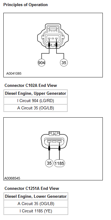
With the key in the ON position (dual generator system), voltage is supplied by the powertrain control module (PCM)-controlled I circuit 1183 (WH/YE) / 904 (LG/RD) to the upper generator and through the I circuit 1185 (YE) to the lower generator. If the glow plug system is not cycling, the PCM maintains power to the lower generator. If the glow plug system is cycling, the PCM supplies power to the lower generator momentarily to verify there is a volt drop, then shuts off the power on the lower generator I circuit 1185 (YE). Once the glow plug system stops cycling, the PCM supplies power on the lower generator I circuit 1185 (YE), which turns the regulator on allowing current to flow from the battery sense A circuit to the generator field coil, at which time it begins to function normally. The PCM maintains power on the upper generator I circuit 1183 (WH/YE) / 904 (LG/RD), which turns on the regulator, allowing current to flow from the battery sense A circuit to the generator field coil.
Once the generator begins generating current, a voltage signal is taken from the generator stator and fed back to the regulator internally. This voltage feedback signal (typically one-half of the battery voltage) is used by the PCM to turn off the charging system warning indicator.
With the system functioning normally, the generator output current is determined by the voltage of the A circuit 35 (OG/LB). The A circuit 35 (OG/LB) voltage is compared to a set voltage internal to the regulator, and the regulator controls the generator field current to maintain the correct generator output.
The set voltage varies with temperature and is typically higher in cold temperatures and lower in warm temperatures. This allows for more efficient battery recharge in the winter and reduces the chance of overcharging in the summer.
Positive Battery Output (B+) Circuit 1119 (RD) (Upper) / Circuit 36 (YE/WH) (Lower)
The generator output is supplied through the positive battery output (B+) terminal on the rear of the generator to the battery and the electrical system.
I Circuit — Dual Generator
The I (ignition) circuit is used to turn on the voltage regulator(s). This circuit is powered up when the key is in the ON position. When the PCM detects key ON, the PCM provides power to the upper generator I circuit 1183 (WH/YE) / 904 (LG/RD) and also to the lower generator I circuit 1185 (YE). The power to the lower generator is only momentary unless the glow plug system is not cycling. Once the glow plugs stop cycling, the PCM provides constant power on the lower generator I circuit 1185 (YE).
A Circuit 35 (OG/LB)
The A circuit or battery sense circuit is used to sense battery voltage. This voltage is used by the regulator to determine generator output.
Inspection and Verification
WARNING: Batteries contain sulfuric acid. Avoid contact with skin, eyes, or clothing. Also, shield your eyes when working near batteries to protect against possible splashing of the acid solution. In case of acid contact with skin or eyes, flush immediately with water for a minimum of 15 minutes and get prompt medical attention. If acid is swallowed, call a physician immediately. Failure to follow these instructions may result in personal injury.
WARNING: Batteries normally produce explosive gases. Therefore, do not allow flames, sparks or lighted substances to come near the battery. When charging or working near a battery, always shield your face and protect your eyes. Always provide ventilation. Failure to follow these instructions may result in personal injury.
WARNING: When lifting a battery, excessive pressure on the end walls could cause acid to spew through the vent caps, resulting in personal injury, damage to the vehicle or battery. Lift with a battery carrier or with your hands on opposite corners. Failure to follow these instructions may result in personal injury.
NOTICE: Do not make jumper connections except as directed. Incorrect connections may damage the voltage regulator test terminals, fuses, or fusible links.
NOTICE: Do not allow any metal object to come in contact with the generator housing and internal diode cooling fins. A short circuit may result and burn out the diodes.
NOTE: While carrying out any pinpoint test, disregard the diagnostic trouble codes (DTCs) set while following the specific pinpoint test. After the completion of any test, be sure to clear all DTCs in the PCM.
NOTE: All voltage measurements are referenced to the negative (-) battery post unless otherwise specified.
NOTE: The dual generator I circuit/bulb circuit 4-way connector MUST be connected before disconnecting or connecting the battery. The PCM relearns its parameters every time it is disconnected and connected to power. Failure to follow this procedure causes the PCM to misinterpret the charging system as a single generator system, causing loss of DTC capability and control.
Functionality
With the key in the ON position (dual generator system), voltage is supplied by the powertrain control module (PCM)-controlled I circuit 1183 (WH/YE) / 904 (LG/RD) to the upper generator and through the I circuit 1185 (YE) to the lower generator. If the glow plug system is not cycling, the PCM maintains power to the lower generator. If the glow plug system is cycling, the PCM supplies power to the lower generator momentarily to verify there is a volt drop, then shuts off the power on the lower generator I circuit 1185 (YE). Once the glow plug system stops cycling, the PCM supplies power on the lower generator I circuit 1185 (YE), which turns the regulator on allowing current to flow from the battery sense A circuit to the generator field coil, at which time it begins to function normally. The PCM maintains power on the upper generator I circuit 1183 (WH/YE) / 904 (LG/RD), which turns on the regulator, allowing current to flow from the battery sense A circuit to the generator field coil.
Once the generator begins generating current, a voltage signal is taken from the generator stator and fed back to the regulator internally. This voltage feedback signal (typically one-half of the battery voltage) is used by the PCM to turn off the charging system warning indicator.
With the system functioning normally, the generator output current is determined by the voltage of the A circuit 35 (OG/LB). The A circuit 35 (OG/LB) voltage is compared to a set voltage internal to the regulator, and the regulator controls the generator field current to maintain the correct generator output.
The set voltage varies with temperature and is typically higher in cold temperatures and lower in warm temperatures. This allows for more efficient battery recharge in the winter and reduces the chance of overcharging in the summer.
Positive Battery Output (B+) Circuit 1119 (RD) (Upper) / Circuit 36 (YE/WH) (Lower)
The generator output is supplied through the positive battery output (B+) terminal on the rear of the generator to the battery and the electrical system.
I Circuit — Dual Generator
The I (ignition) circuit is used to turn on the voltage regulator(s). This circuit is powered up when the key is in the ON position. When the PCM detects key ON, the PCM provides power to the upper generator I circuit 1183 (WH/YE) / 904 (LG/RD) and also to the lower generator I circuit 1185 (YE). The power to the lower generator is only momentary unless the glow plug system is not cycling. Once the glow plugs stop cycling, the PCM provides constant power on the lower generator I circuit 1185 (YE).
A Circuit 35 (OG/LB)
The A circuit or battery sense circuit is used to sense battery voltage. This voltage is used by the regulator to determine generator output.
Inspection and Verification
WARNING: Batteries contain sulfuric acid. Avoid contact with skin, eyes, or clothing. Also, shield your eyes when working near batteries to protect against possible splashing of the acid solution. In case of acid contact with skin or eyes, flush immediately with water for a minimum of 15 minutes and get prompt medical attention. If acid is swallowed, call a physician immediately. Failure to follow these instructions may result in personal injury.
WARNING: Batteries normally produce explosive gases. Therefore, do not allow flames, sparks or lighted substances to come near the battery. When charging or working near a battery, always shield your face and protect your eyes. Always provide ventilation. Failure to follow these instructions may result in personal injury.
WARNING: When lifting a battery, excessive pressure on the end walls could cause acid to spew through the vent caps, resulting in personal injury, damage to the vehicle or battery. Lift with a battery carrier or with your hands on opposite corners. Failure to follow these instructions may result in personal injury.
NOTICE: Do not make jumper connections except as directed. Incorrect connections may damage the voltage regulator test terminals, fuses, or fusible links.
NOTICE: Do not allow any metal object to come in contact with the generator housing and internal diode cooling fins. A short circuit may result and burn out the diodes.
NOTE: While carrying out any pinpoint test, disregard the diagnostic trouble codes (DTCs) set while following the specific pinpoint test. After the completion of any test, be sure to clear all DTCs in the PCM.
NOTE: All voltage measurements are referenced to the negative (-) battery post unless otherwise specified.
NOTE: The dual generator I circuit/bulb circuit 4-way connector MUST be connected before disconnecting or connecting the battery. The PCM relearns its parameters every time it is disconnected and connected to power. Failure to follow this procedure causes the PCM to misinterpret the charging system as a single generator system, causing loss of DTC capability and control.
Thread Starter
|
Senior User
Joined: Dec 2003
Posts: 330
Likes: 0
From: Newhall,CA
Update: I replaced the #2 Alternator and both batteries. The CEL is hasn't come back and the voltage seems good, but I still have no start when it's hot.
The truck runs just fine and HPOP pressure is constant at 580 at idle on up to 4000 when i'm on it. I unplugged the ICP pigtail and still no start when hot, so I'm planning on ripping into the HPOP, upgrading the STC and looking at the O rings.
When hot, I'm hitting around 300PSI during cranking. One video suggested that STC failure won't let it get above 100PSI. Since it's running fine, I'm starting to think it might just be an O ring leak.
Thread Starter
|
Senior User
Joined: Dec 2003
Posts: 330
Likes: 0
From: Newhall,CA
I know I'm digging this out from the grave, but I hate seeing unresolved threads! After replacing both batteries and the 2nd alternator, it ended up being standpipes and dummy plugs. Something might have been wrong with the alt, but it was not the source of the no-start when hot issue.

Thread
Thread Starter
Forum
Replies
Last Post