



Carling switch pin breakdown

Thread Starter
|
Post Fiend
Joined: Sep 2006
Posts: 7,426
Likes: 6
From: Sioux Falls, SD
Carling switch pin breakdown
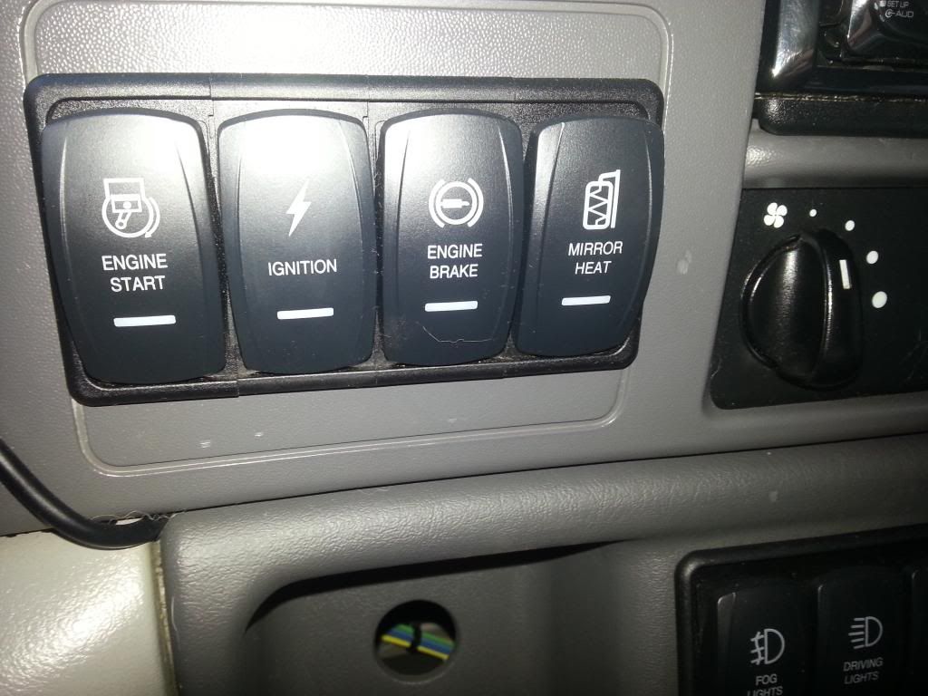
The F-650 dash kit I ordered from Riffraff came with Carling Contura LED Illuminated switches. Can anyone help me with the pin breakdown? I don't want to fry anything .........


Logistics Pro

Joined: Jul 2009
Posts: 3,635
Likes: 3
From: Lansdale, PA
Put your multimeter on it.
I'm guessing that the 3 inline pins, the center pin is 12v, and ones on either side of it go to accessory items. The single one is possibly ground for illumination.
No directions on the riffraff site. Nothing online for the part number or anything. Hmmm
I'm guessing that the 3 inline pins, the center pin is 12v, and ones on either side of it go to accessory items. The single one is possibly ground for illumination.
No directions on the riffraff site. Nothing online for the part number or anything. Hmmm
Logistics Pro
Joined: Jul 2009
Posts: 3,635
Likes: 3
From: Lansdale, PA
Posting Guru
Joined: Jan 2013
Posts: 2,215
Likes: 2
From: North Lake Tahoe
Here you go.
Its a little confusing but once mastered it's pretty easy to figure out let me know if you have any Q's.
1st pic is for your basic on off switch. On/Off.

2nd pic is if you have two different accessories on one switch. On/On/Off.
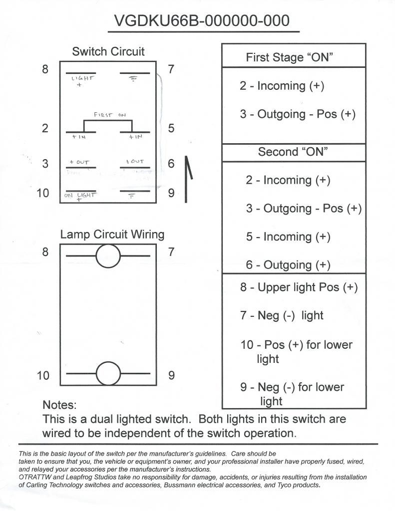
Its a little confusing but once mastered it's pretty easy to figure out let me know if you have any Q's.
1st pic is for your basic on off switch. On/Off.

2nd pic is if you have two different accessories on one switch. On/On/Off.

Posting Guru
Joined: Jan 2013
Posts: 2,215
Likes: 2
From: North Lake Tahoe
Basic on/off switch
8, power feed for when dash lights come on
7, ground feed
2, hot coming in from fused/relay power source
3, going out to your accessory Lights, air comp., etc.
6, ground feed can be tied into 7.
8, power feed for when dash lights come on
7, ground feed
2, hot coming in from fused/relay power source
3, going out to your accessory Lights, air comp., etc.
6, ground feed can be tied into 7.
Thread Starter
|
Post Fiend
Joined: Sep 2006
Posts: 7,426
Likes: 6
From: Sioux Falls, SD
Trending Topics
Posting Guru
Joined: Jan 2013
Posts: 2,215
Likes: 2
From: North Lake Tahoe
FTE Stories
Ford Trucks for Ford Truck Enthusiasts

Top 10 Most Expensive Ford Trucks Ever Sold on Bring a Trailer
Joe Kucinski
2027 Ford Super Duty Buyer's Guide (Every Model, Engine, & Package)
Brett Foote
Top 10 Ford Truck Tragedies
Joe Kucinski
AEV FXL Super Duty - the Super Duty Raptor Ford Doesn't Make
Brett Foote
Lobo Vs Lobo: Proof the F-150 Lobo Should Be Even Lower!
Michael S. Palmer
Ford's 2001 Explorer Sportsman Concept Looks For a New Home
Verdad Gallardo
10 Best Ford Truck Engines We Miss the Most!
Joe Kucinski
2026 Shelby F-150 Off-Road: Better Than a Raptor R?
Brett Foote
2027 Super Duty Carhartt Package First Look: 12 Things You NEED to Know!
Michael S. Palmer
Posting Guru
Joined: Jan 2013
Posts: 2,215
Likes: 2
From: North Lake Tahoe
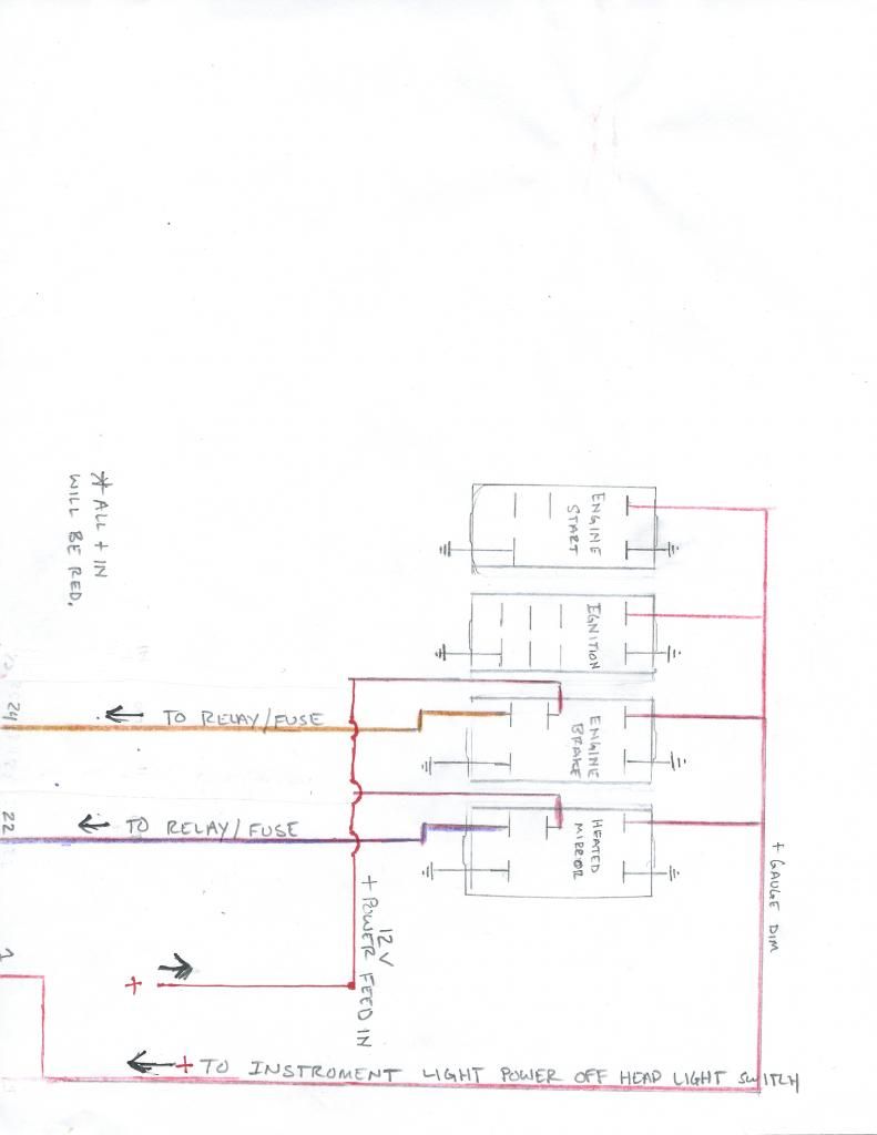
So I hope that this doesn't confuse anyone. I have no problems answering any questions and plan on cleaning all this up soon so it's more professional.
Some rough sketches of my wiring diagram.
The dome/floor light switch is a 3 way switch. off/on/on (off / floor lights / dome light)
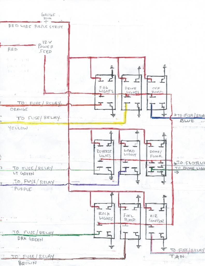
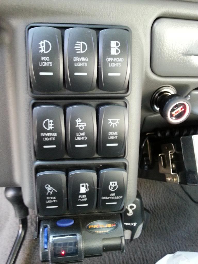
No need to pay attention to "actual colors on truck" those are just my notes of what colored wires I used. Did the sketch before I ordered wires.
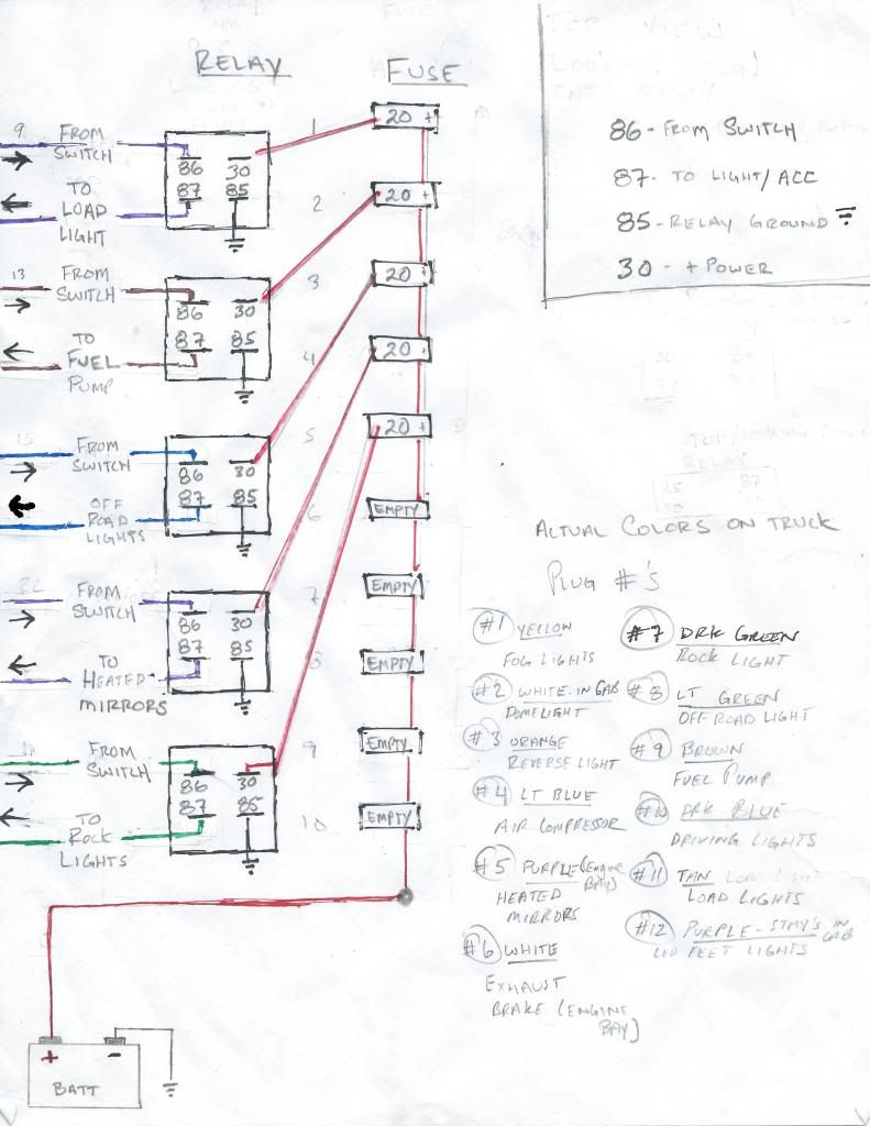
[/URL]
Some rough sketches of my wiring diagram.


The dome/floor light switch is a 3 way switch. off/on/on (off / floor lights / dome light)


No need to pay attention to "actual colors on truck" those are just my notes of what colored wires I used. Did the sketch before I ordered wires.

[/URL]


Hotshot


Joined: Jan 2011
Posts: 18,849
Likes: 179
From: Puget Sound
If the picture in the OP does not accurately represent what Clay sends, disregard the following:
Whoa! Putting a pause on things here:
The switch in the picture has 4 terminals. All the diagrams show 5 terminals or more.
I looked at the whole Carling catalog - cool products, complex options, and missing data on this switch.
I have installed many lighted switches, and the light typically gets its power from the load side of the switch... meaning no light dimmer.
With conflicting info, my gut is telling me the three terminals in a row are single-pole double-throw. Power would go to the middle terminal, and the load would go on one of the two end terminals. One of the end terminals is attached to one end of the LED, and that one lone terminal to the side is ground for the LED.
Oh... side note: Check this out.
https://www.youtube.com/watch?v=EySK...ature=youtu.be
I have a test - 12V on the center terminal of the three in a row. Ground to the straggler not in line. Flip switch. If the LED lights up, my gut was right.
Whoa! Putting a pause on things here:
The switch in the picture has 4 terminals. All the diagrams show 5 terminals or more.
I looked at the whole Carling catalog - cool products, complex options, and missing data on this switch.
I have installed many lighted switches, and the light typically gets its power from the load side of the switch... meaning no light dimmer.
With conflicting info, my gut is telling me the three terminals in a row are single-pole double-throw. Power would go to the middle terminal, and the load would go on one of the two end terminals. One of the end terminals is attached to one end of the LED, and that one lone terminal to the side is ground for the LED.
Oh... side note: Check this out.
https://www.youtube.com/watch?v=EySK...ature=youtu.be
I have a test - 12V on the center terminal of the three in a row. Ground to the straggler not in line. Flip switch. If the LED lights up, my gut was right.

Super Moderator


Joined: May 2004
Posts: 29,380
Likes: 118
From: Central Coast of CA

Here's the post:
Here you go Clint, sorry I didnt see this thread sooner.

now, what this diagram doesn't tell you is that you need to daisy chain your switches together, if you are running mor ethan one switch. that way you only have to have one positive wire, one ground wire, and one positive illumination wire running to one switch and then you can wire the switches in series to all use the same power and ground wires...... Clear as Mud?
#8 connects to Illum +, and then run a jumper to the #8 pole on the second switch, and a jumper to the #8 pole on the third switch.
#7 connects to ground -, and then a jumper to #7 pole second switch, and a jumper to #7 pole third switch
#2 connects to 12V+ switched power, and then a jumper to second switch #2 pole, and then jumper to third switch #2 pole.
#3 pole is your output to what ever ACC you are using the switch for. DO NOT DAISY CHAIN # 3 POLE.
now, what this diagram doesn't tell you is that you need to daisy chain your switches together, if you are running mor ethan one switch. that way you only have to have one positive wire, one ground wire, and one positive illumination wire running to one switch and then you can wire the switches in series to all use the same power and ground wires...... Clear as Mud?
#8 connects to Illum +, and then run a jumper to the #8 pole on the second switch, and a jumper to the #8 pole on the third switch.
#7 connects to ground -, and then a jumper to #7 pole second switch, and a jumper to #7 pole third switch
#2 connects to 12V+ switched power, and then a jumper to second switch #2 pole, and then jumper to third switch #2 pole.
#3 pole is your output to what ever ACC you are using the switch for. DO NOT DAISY CHAIN # 3 POLE.
Thread Starter
|
Post Fiend
Joined: Sep 2006
Posts: 7,426
Likes: 6
From: Sioux Falls, SD
Thanks for the help, info & diagrams guys - gonna try and get this all finished today since it's gonna be nice out today (65 degrees!) and I won't have to hide in the garage with the heater.
Rich (Tugly), yep - the switches I ordered are the ones I posted the pic of in my OP. I tried to decipher the technical diagrams on Carlings website - but after 2 beers it was too much for my brain at the time..... You can order any type of switch through Riffraff when ordering the F650 dash kits but I just needed the easy & simple on/off switches - but the switch on lamp and the background LED through me off I guess.......
Either way I need to finish today since more snow is coming Monday g
g
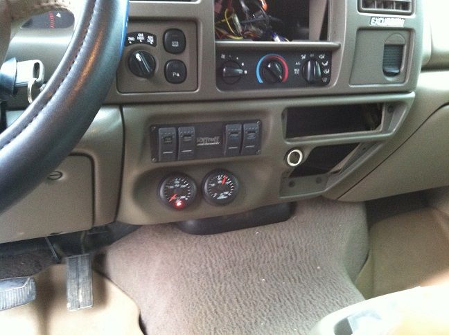
Rich (Tugly), yep - the switches I ordered are the ones I posted the pic of in my OP. I tried to decipher the technical diagrams on Carlings website - but after 2 beers it was too much for my brain at the time..... You can order any type of switch through Riffraff when ordering the F650 dash kits but I just needed the easy & simple on/off switches - but the switch on lamp and the background LED through me off I guess.......
Either way I need to finish today since more snow is coming Monday
g
Thread Starter
|
Post Fiend
Joined: Sep 2006
Posts: 7,426
Likes: 6
From: Sioux Falls, SD
Clay does a nice job with his products - doesn't he........
Can't believe it has taken me 3 years to get this stuff done on the Excursion. Boy, that fuel pressure gauge sure got more eyeball time than any other gauge this incredibly cold winter . It sure is nice to have it finally mounted instead of dangling from the dash.....
Can't believe it has taken me 3 years to get this stuff done on the Excursion. Boy, that fuel pressure gauge sure got more eyeball time than any other gauge this incredibly cold winter
. It sure is nice to have it finally mounted instead of dangling from the dash.....
Thread Starter
|
Post Fiend
Joined: Sep 2006
Posts: 7,426
Likes: 6
From: Sioux Falls, SD
Thanks everybody - got her all buttoned up before the next round of snow is due to hit.
