
1951 F1 Flathead Clutch Linkage Question

Cargo Master


Joined: Jun 2001
Posts: 2,571
Likes: 22
From: Oxford, Indiana

To come up with that much difference in linkage position, I'd say you don't have something together right in there. In its "at rest" position, the throw out bearing assembly will stop in the same position every time regardless of what you've got in there for a clutch. You shouldn't have any trouble getting the linkage hooked up. Don't cut anything until you've seen what's going on in there. I suspect that the fork might be in front of the bearing instead of behind it or some such thing. There should also be a spring in there that pulls the bearing back towards the transmission. Make sure that spring is in place also. It helps keep the bearing in the proper position relative to the fork.


Thread Starter
|
Senior User
Joined: Sep 2011
Posts: 361
Likes: 0
From: PA, North of Pittsburgh
Thanks for the pictures Dick. I will go down and compare once my heater warms the garage up!
Blue Oval Rage, I am almost positive I put this together the right way inside the bell. I remember pushing the fork back against the trans, sliding on the bearing hub and throwout bearing and the 2 pieces not meshing quite right so I had slide the fork bar outside the transmission a little bit and then the hub slid right against the fork. I bought a new spring and put it on the hub back to the trans.
When you turn the clutch fork shaft ear it moves forward a little bit and does spring back into the same place everytime.
With the clevis adjusted all the way in I can almost get the pin in but I know the throw out bearing is not rested against the trans, its as far forward as I can turn it and I dont want to hook it up that way. I think there should be some slack so the clutch fully engages/ disengages.
How much of this will I be able to see with the inspection cover removed?
Cargo Master
Joined: Jun 2001
Posts: 2,571
Likes: 22
From: Oxford, Indiana
It does sound like you've got it together right. Keep in mind that in normal service after everything is properly adjusted, the bearing and hub never come all the way back to the stop. The stop is the pedal hitting the bumper on the floor. The freeplay adjustment that's giving you grief should be set up so that the bearing is held in a position close to but not touching the fingers on the clutch cover. If I'm understanding your problem, the bearing is coming in contact with the fingers before you can even get the linkage assembled. I recently had a similar but opposite problem with a Ford 8N tractor that I did some clutch work on. The clutch mechanism in that machine is the same rotating shaft and fork arrangement as in these trucks. Your new disk might be too thin or your pressure plate might have been machined one too many times. The thinner the disk or pressure plate are, the farther away from the flywheel the fingers will be once the clutch is bolted to the flywheel. I had the opposite problem with my tractor - With the adjustment all the way out I just barely had enough pedal travel to disengage the clutch. I traced it back to a mismatched disk and pressure plate assembly from a combination of NOS and aftermarket parts. I'd be looking hard at the clutch now. Something just doesn't sound right here. Unfortunately, you're probably going to have to pull it to see what's up.

Welder User

Joined: Feb 2009
Posts: 5,269
Likes: 49
From: northwest MT
i agree with BOR....it is likely the stacked height of your new clutch is different. Either thicker or thinner. The PP could be designed slightly different as well.
I would make a temporary threaded link from some redi-bolt, hook it up and make sure the clutch is working right. If so, modify your link as needed and go on. If not, some other problem exists......
I would make a temporary threaded link from some redi-bolt, hook it up and make sure the clutch is working right. If so, modify your link as needed and go on. If not, some other problem exists......
Fleet Owner


Joined: Jul 2004
Posts: 27,266
Likes: 1,027
From: NM
If it's still got the Long-type clutch (3 fingers) it's also possible the bolts on the fingers are adjusted too far out or in (I can't figure which way). I think there may be a spec for finger height in the workshop manual.
Thread Starter
|
Senior User
Joined: Sep 2011
Posts: 361
Likes: 0
From: PA, North of Pittsburgh
BOR, You are exactly right, if I had about a 1/4" more adjustment with that clevis it would all go together correctly and the throwout bearing would be adjusted forward and not resting back against bthe trans
I did have the flywheel machined
The clutch is the 3 finger type, I didnt adjust the bolts I figured they were where they were supposed to be. It is brand new and I bought it from Dennis Carpenter
The clutch is an 11" clutch, thats what the flywheel was drilled for. I am thinking the motor is from an F2 or F3 maybe? Since I think I read the F1 had a 10"
Thread Starter
|
Senior User
Joined: Sep 2011
Posts: 361
Likes: 0
From: PA, North of Pittsburgh
I did not take the clutch fork off of the trans.
I pulled the inspection cover and everything looks perfect. The fork was perfectly against the throw out bearing hub, the bearing hub had the spring connected correctly, and the bearing hub assembly slid nice and smooth on the input shaft.
My friend came over to give me a hand and he has the outlook of" its not my truck so lets get in there and fix it".
We bolted the equalizer tube to the trans and to the ball socket.
We rotated the equalizer tube as far forward as we could until the throwouit bearing was almost touching the clutch fingers. The clevis was still way off but we screwed it as far on the shaft as we could, the threaded shaft is almost touching the part of the clevis where the pin goes through but we got the pin in.
We pushed the clutch pedal and it all seems to move without any binding. Now I will say the clutch fork tube does not rotate very far but that is controlled by the clutch pedal pivot, not the clevis.
With the clutch not pressed the throwout bearing is able to spin with your fingers, this relieved me because I know the bearing is not pushing on the fingers until the pedal is pushed.
I didnt try to drive the truck because it still needs wired so Im not sure if it is all working for sure or not.
Thanks everyone for all of your suggestions!!!!!
Fleet Owner
Joined: Jul 2004
Posts: 27,266
Likes: 1,027
From: NM
With the pedal to the floor, is the clutch completely released? Only way to test is either jack up a rear wheel and spin it in with the trans in gear, or start the engine and listen for teeth shucking off when you move the lever... (Edit -- with the inspection cover off, you might be able to see if the disc is free when the pedal is pressed)
I'd be concerned that with the bellcrank so far forward, you don't get the twist you need, because the bellcrank angle is way off center.
I'd be concerned that with the bellcrank so far forward, you don't get the twist you need, because the bellcrank angle is way off center.
Thread Starter
|
Senior User
Joined: Sep 2011
Posts: 361
Likes: 0
From: PA, North of Pittsburgh
That was my big concern too, I tried pushing the pedal to the floor and with the trans in first gear the truck did not roll as if it was in neutral.
Should it roll completely free?
I was hoping with it running it would all just work ok.
I am completely clueless if it is supposed to roll completely free.
Under that inspection cover everything was hooked up right, The ball socket only bolts in 1 place, the equalizer tube only hooks up 1 way, and the pedals only bolt to the frame 1 way. I dont see how any of this could have changed.
I did have the pedals out to paint them but I dont see how that would have affected anything.
The only thing that is different is a machined flywheel, new 11" clutch, and a transmission from a 48 panel
Thread Starter
|
Senior User
Joined: Sep 2011
Posts: 361
Likes: 0
From: PA, North of Pittsburgh
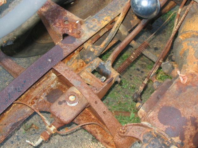
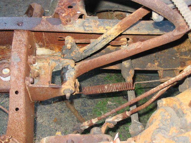
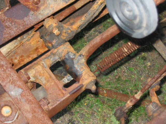
If you look at the third picture in 4tl8ford earlier post his equalizer tube has an arm that connects to the clevis and points at about the noon position.
My equalizer tube arm is at about the 10 oclock poition, Thats why I needed to screw the clevis on so far.
What would make my arm be in a different position than the one in his picture?
Is it possible the person that worked on this transmission last put the clutch fork on the clutch fork tube wrong? I looked at a new clutch release tube from macs and the hole the fork is mounted to does not line up perfectly with the flat part at the end where the equalizer bolts to. So it appears the fork could connect 2 different ways making the tube end be at a different angle depending where the fork was connected.
I hope that last part makes sense
Fleet Owner
Joined: Jul 2004
Posts: 27,266
Likes: 1,027
From: NM
Yes, and yes. Someone could have replaced your equalizer tube with one from something else, and although it's unusual to remove the clutch fork from the tube, it can be done and could have been put on backwards. Pic shows mine, both fully assembled (so you can see which orientation the "key" on the clutch fork shaft is in) and a pic that shows the orientation of the fork.