When you click on links to various merchants on this site and make a purchase, this can result in this site earning a commission. Affiliate programs and affiliations include, but are not limited to, the eBay Partner Network.
87-Anyone know TRUE location of coolant temp sender? NO 'they' don't!
STOP RIGHT HERE: I was wrong! I was wrong because of a significant error in the official 1987 Ford Light Tuck Shop Manuals, specifically the Electrical & Vacuum Troubleshooting manual which is the manual that contains the component wiring diagrams and schematics. (vacuum lines also) for gas and diesel trucks/vans/broncos. The diagram/schematic showing the wiring for the coolant temperature senders, one for the Coolant Temperature Gauge (the sender to the right of the timing cover) is MISLABELED AS THE 'OVERHEAT WARNING SWITCH'. The other sender below the front end of the valve cover at the driver's side in the wiring diagram, IS NOT A SENDER although it looks like one and senses temperature, it is a TEMPERATURE SWITCH. This switch is MISLABELED AS THE 'COOLANT TEMPERATURE SENDER.' This was the cause of my confusion and apparently I am not the only one who has been confused by it.
A lines drawing of the engine on another page, (also posted below) shows the location of these senders on the engine. SO, the wiring colors/tracers in the schematic are correct and only the coolant temperature sender and overheat warning switch are mislabeled.
I also discuss where the wires go (beyond what is shown in the schematic) but this topic is only useful for knowing the correct location of the sender and switch, tracing the wires that come from them and knowing that the schematic in the manual is mislabeled. Beyond that there is a lot of nonsense that I am going to edit and remove so people wont have to read it and it stays to the point.
ALSO, a big THANK YOU to 'NumberDummy' Bill / Retired Ford Parts Manager / SoCal Chapter Member / for doing a search and posting the actual parts drawing.
(My truck is 1987)
Last night I was outside getting ready to install my THIRD engine coolant sensor ---> to the GAUGE for the second time since February because the gauge has not worked. Out of three previous new wrong sensors or wrong locations - this will be the fourth purchased.
I decided to check the wire colors on the two different 'temperature related' senders on the driver's side of the engine to check and confirm the connections and wire colors from the gauge cluster schematic.
(paragraphs removed on Edit) )
Suffice it to say, that the Coolant Temperature Sender specified for that location on 83-89 trucks(etc.) as shown in the parts drawing posted by 'NumberDummy, is the right one The other senser to the warning module/warning light is a switch a larger diameter and won't fit at this location. 1990 and later trucks could could have different parts drawing or specifications according to the title of that drawing that drawing.
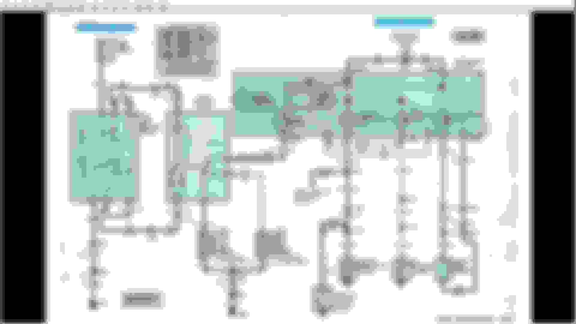
The image from the manual where only the labels of the senders are reversed:
Instrument cluster and sensors, partial schematic<br/>
That schematic is actually from the Electrical & Vacuum Troubleshooting Manual, THIS is where to go for schematics, NOT the Body, Chassis Electrical Manual which is over 1600 pages.
Break time. I wish I had the energy to tell you the story about when I decided to give up motor vehicles altogether and get a DONKEY! Heee-Haaaw.
I actually did get get a big Donkey named Lulu, mostly wild and untamed. I was training her to pack in the mountains. It's a beautiful story!
I didn't give up on motor vehicles though and where would I be now If I had done so?
Maybe living a beautiful and stress-free life out in a remote area of the mountains, under the stars at night with animals and the forces of nature and the cosmos as my guides to heaven.
The Black/Light-Blue tracer wire that is spliced into the wire going to the temp Gauge goes through a diode to the ignition switch, and on to the Water in Fuel Switch which closes if there is water in the sedimenter bowl which then lights the 'Water In Fuel" light.
The wires from the temp sender and the overheat warning switch (into one wire White/Light Blue) to the Gauge goes through the Gauge and on to the 'Engine Warning Indicator Module' and the 'Engine Warning Indicator Light,' - I assume when a temperature gauge is not present the circuit is to the warning module and the light. Or maybe they are both circuits are functional with a gauge installed.
I scrolled through 60 pages taking screen shots of wiring diagrams that I need for various things before I got to page 85, which doesn't show anything new for this issue- it just directed me on to Page 97, which I scrolled to looking at every image for diesels all the while (gas engines too) for a total of about 76 pages. I forgot what is on page 97 - (How could I forget!!) some additional things there but nothing important for this issue. I explained it in the first paragraph.
So, where does that leave us?
I THINK MY GAUGE IS SCREWED UP AND DOESN'T WORK! Not the sender or the warning light switch!
If I can get this truck where I intend to take it when I move, (wherever that is because I haven't decided yet) maybe I can park it and have a Donkey Too!
THANK YOU VERY MUCH! Same Line Drawings that I posted (Colorized) but yours have reference numbers.
Are those reference numbers part of (within) the actual part numbers and can be used to identify parts or do they refer to an index?
The images I posted are from a fully licensed and authorized scan from 2008 of the 1987 Ford Shop Manuals for Light Truck/Bronco/Econoline. 5 manuals including 'Pre-Delivery for Cars/Trucks Light Medium Heavy. Over 3,600 pages with a lot of detail and text for the service mechanics.
EDIT: Remove paragraphs
I trust that your parts drawing and the line drawings in my manual must be right.
Sorry if I seemed grumpy, I've been on these forums for (Oh No!) over 21 hours straight with only a few 15 minute breaks. (that happens too often) I do find some humor in all all of this.
After about 10-12 hours I go into an auto-pilot mode and keep reading researching, typing until I find myself typing in a dream-state. (Like now) It's actually a very creative state of mind but I must refrain! Then it's too late to change anything I've written. So, it's time for me to stop, wake up and go to sleep.
So, the picture of the red and silver engine was right after all. I thought my apology was implied about half way through. Tomorrow (today sometime) I will edit my very first post to state at the beginning that this was a wild goose chase due to a substantial error in the 'official' 1987 Shop Manuals- the Electrical and Vacuum Troubleshooting Manual (to be more precise)...
If you have just noticed this topic or arrive here I am editing the whole thread from the first post on. The first post now begins with:
STOP RIGHT HERE: I was wrong! I was wrong because of a significant error in the official 1987 Ford Light Tuck Shop Manuals, specifically the Electrical & Vacuum Troubleshooting manual... My posts in the whole thread have been edited and shortened.
THANK YOU VERY MUCH! Same Line Drawings that I posted (Colorized) but yours have reference numbers.
Are those reference numbers part of (within) the actual part numbers (see below) and can be used to identify parts or do they refer to an index?
Only Ford basic part numbers are shown in illustrations.
The text section of the parts catalog is required to get the complete part number by adding the apropos prefix and suffix to the basic part number.
DOZZ-10884-A .. Water Temperature Sending Unit Switch (Motorcraft SW-925) / Available from Ford
MSRP: $43.02 / FTE Ford dealer parts dept sponsor horizonpartsguy.com online price: $26.24 / Horizon Ford Truck Center - Seattle (Tukwila) WA
------------------------------------------------------------------------------------------------------------------------------------------------------------------- F3TZ-10884-A (replaced E3TZ-10884-A) .. Water Temperature Indicator Lamp Switch / Marked with ID engineering number: E3TF-10B843-AA (Motorcraft SW-2520) / Available from Ford
 09-15-2015, 11:41 PM