1996 Instrument Cluster Help
Posting Guru
Joined: Aug 2007
Posts: 1,025
Likes: 1
From: Colorado Springs
the easiest way to know if this is going to work in your truck is going to be to plug it in and try. instructions for install incase you need them..
grab the **** for the lights pull on it till the lights turn on then pull a little more and it should pop off.
next grap a flat head screw driver or similar and insert between dash and gauge bezel should only take slight pressure and the clips should pop out. finish removing bezel and unhook any wires attached.
remove the screws holding the guage set in (cant remember how many exacly) you only need to remove the ones that are on the black part the ones in the clear plastic dont need to be removed
then pull guage twards you (may need to drop sterring wheel to lowest position) after guages are out far enough un hook the two connectors on the back.
plug in new set and slide into position there is no need to reassembe every thing at this point.
start truck and look at guages main to to look at are the tac and voltage. if truck dosnt die after 10-20 minutes your good. if truck does die reinstall old guage and jump it off becasue your battery is dead.
Fleet Owner


Joined: Aug 2005
Posts: 23,667
Likes: 301
From: Easton,Ks


Instrument Cluster Display Proveout
When the key is turned to RUN, the following warning lamps will prove out by momentarily lighting.
safety belt
charging system
air bag
brake system
anti-lock brake
check engine lamp
Printed Circuit
The instrument cluster printed circuit (10K843), which supplies current to the instrument panel indicators, gauges, and some clocks, is made of copper foil that is bonded to a polyester base film (usually referred to as Mylar�).
The instrument cluster printed circuit is mounted to the cluster housing and, due to its location, cannot be easily inspected or tested in the vehicle. This makes the instrument cluster printed circuit vulnerable to damage when a probe is used for in-vehicle testing as the probe can pierce the instrument cluster printed circuit or, in some cases, burn the copper conductor.
Since there is no approved procedure for in-vehicle testing of the instrument cluster printed circuit, it must be removed for visual inspection. If no visual damage is evident, each circuit should be tested with an ohmmeter. If an open circuit or short is detected, the instrument cluster printed circuit must be replaced.
Fleet Owner
Joined: Aug 2005
Posts: 23,667
Likes: 301
From: Easton,Ks
Warning Indicators
Brake System
All vehicles use a brake warning light in the instrument cluster (10849) to warn of system malfunctions. The red warning light for the brakes can indicate three conditions:
the parking brake is not fully released
the brake fluid level is low in the master cylinder reservoir
the vacuum pressure is low on diesel engine vehicles
Rear Anti-Lock Brakes
The yellow anti-lock brake indicator lights up for approximately two seconds when the key is first moved to RUN or START for circuit proveout. The indicator also lights up when the RABS module detects a malfunction in the system.
The self-test feature contains codes that indicate the area of the malfunction. When a malfunction is detected, the RABS control module shuts down the system and the yellow anti-lock warning indicator comes on. This permits normal braking. A code can be retrieved by momentarily grounding the diagnostic pigtail (black with orange stripe wire) after it is disconnected from KAM (keep-alive power red wire) and counting the flashes of the yellow ABS lamp. To make sure the diagnostic trouble code (DTC) is not lost from memory, the key must be left in the RUN position before the diagnostic lead is disconnected from KAM power. If more than one diagnostic trouble code exists, only the first code stored will be displayed. Additional codes will be output only after the first fault is corrected.
Check Engine (MIL)
The check engine warning indicator comes on when the electronic engine control system is not working properly.
The CHECK ENGINE warning indicator comes on briefly when the key is turned to RUN, and should turn off when the engine (6007) starts. If the CHECK ENGINE warning indicator does not come on when the key is turned to RUN or if it comes on while the vehicle is moving, the system is malfunctioning.
Note:
If the vehicle is equipped with dual fuel tanks (9002), the CHECK ENGINE light may come on if fuel is restricted to the engine or if the fuel flow is momentarily disrupted because of an empty fuel tank before switching to the auxiliary fuel tank. This condition is normal and the CHECK ENGINE light should go off sometime after fuel flow is restored.
Charging System
The charge indicator lights if the voltage in the integral generator drops below a preset level while the key is in RUN.
The charge indicator light comes on every time the key is turned to RUN or START. The light should go off when the engine starts and the generator (GEN) (10346) begins to charge.
Air Bag (if Equipped)
The air bag warning indicator will illuminate for six seconds when the key is turned to the RUN position. If the air bag warning indicator fails to illuminate, continues to flash, remains on, or if a series of five beeps is heard, the system requires service.
Safety Belt
The safety belt warning light reminds the driver to fasten safety belt. Each time the key is turned to RUN, the warning light will come on for a short time to remind the driver to fasten the safety belt.
High Beam
The high beam indicator comes on when the headlamps are turned on high beam or when the headlamps are flashed, and indicates that the headlights are illuminated at reduced intensity for daytime running lamps.
LH/RH Turn
The LH/RH turn signal indicators are located in the instrument cluster. If the turn signal indicator light in the instrument cluster does not illuminate or remains on (does not flash) when a turn is signaled, the turn signaling system is malfunctioning.
Overdrive/Overdrive Off
The OVERDRIVE OFF indicator lights when the transmission is locked out of OVERDRIVE. This is done by pressing the switch button in the end of the gear selector lever.
Electronic 4-Wheel Drive
A 4x4 indicator light and a LOW RANGE indicator light are located at the lower right of the instrument cluster. In addition, two small amber lights are located near the Touch Drive buttons. The amber light to the left of the 4x4 button will light up at the same time as the 4x4 instrument cluster light. The amber light to the left of the LOW RANGE light will light up at the same time as the instrument cluster LOW RANGE light.
4x4 High Range
When the 4-wheel drive high range is engaged, the switch closes at first contact and the 4x4 HIGH RANGE lamp illuminates. When the low range is engaged, the switch closes a second contact and the low range bulb illuminates at the same time as the 4x4 LOW RANGE lamp illuminates.
4x4 Low Range
The 4x4 low and high lamp circuit consists of two indicator lamps located on the instrument cluster and a switch located in the transfer case. One lamp indicates when the vehicle is in the 4-wheel drive high range position (4H) and one lamp indicates when the vehicle is in the 4-wheel drive position (4L).

Thread Starter
|
Tuned
Joined: Aug 2004
Posts: 269
Likes: 0
thanks, i read all about the light functions in the manual last night for the heck of it. i know the true test is getting it in the truck and seeing what happens - which is what i will do this weekend. was just wondering if there is a clear determination on whether or not the cluster is a 96 model based on part numbers and/or idiot light configuration.
just for kicks, can anyone with a 92-95 f series/bronco tell me if the brake light on their dash has a (!) or a (P) after it?
just for kicks, can anyone with a 92-95 f series/bronco tell me if the brake light on their dash has a (!) or a (P) after it?
Fleet Owner
Joined: Aug 2005
Posts: 23,667
Likes: 301
From: Easton,Ks
And on one out of a 95 the number starts with F4 on printed circuit.
The case starts with an F2.

Cargo Master

Joined: Mar 2007
Posts: 2,935
Likes: 34
From: Arcadia, Fla
Lots of good info here! But I have a 95 (96 titled) E350 Bus conversion I want to put in a F series cluster with tach in its place. Does anybody know if the E-series and F-series clusters were the same? I was told they will fit in with wire changes.
Fleet Owner
Joined: Aug 2005
Posts: 23,667
Likes: 301
From: Easton,Ks
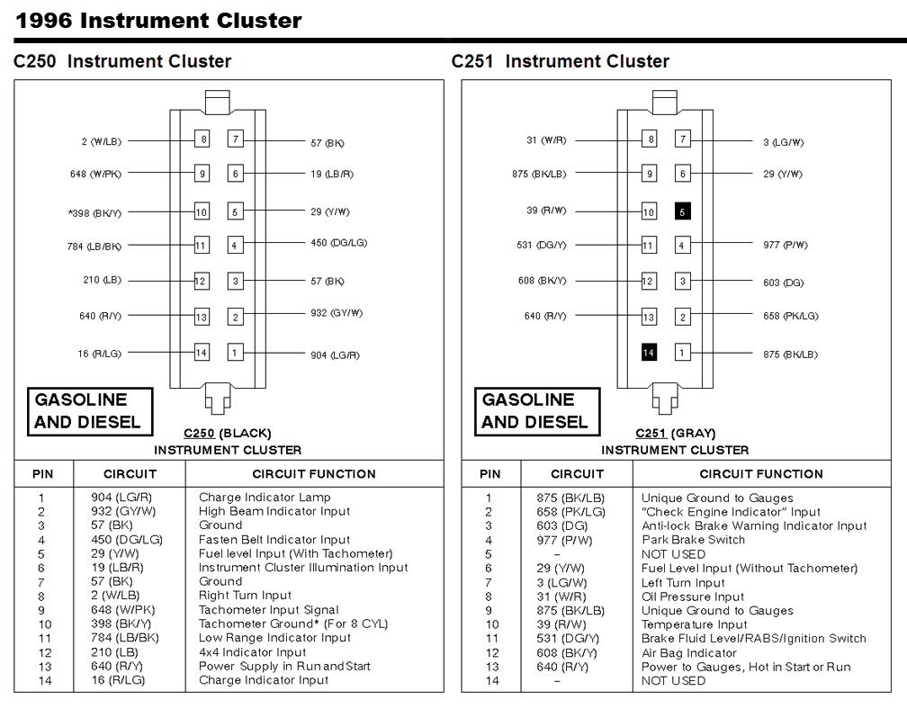
If you need a wiring diagram of each email me but I will link you to the pin-outs for the 95 E & F series cluster plugs.
E-series:
http://i54.photobucket.com/albums/g9...C23395-96E.jpg
F-series:
http://i54.photobucket.com/albums/g9...50-C25195F.jpg
/
Cargo Master


Joined: Mar 2003
Posts: 2,333
Likes: 296
BRAKE
(!) (P)
This light signals more than just parking brake,it signals a brake failure too.
If the light is bright, it is usually the parking brake and if it isn't as bright, it usually signifies a brake problem.
A brake problem quite often will set off the ABS light too.
FTE Stories
Ford Trucks for Ford Truck Enthusiasts

10 Things Every Truck Owner NEEDS (2026 Edition)
Michael S. Palmer
Rezvani's Latest Post-Apocalyptic Monster Is a Ford F-150 Raptor Underneath
Verdad Gallardo
Top 10 Most Expensive Ford Trucks Ever Sold on Bring a Trailer
Joe Kucinski
2027 Ford Super Duty Buyer's Guide (Every Model, Engine, & Package)
Brett Foote
Top 10 Ford Truck Tragedies
Joe Kucinski
AEV FXL Super Duty - the Super Duty Raptor Ford Doesn't Make
Brett Foote
Lobo Vs Lobo: Proof the F-150 Lobo Should Be Even Lower!
Michael S. Palmer
Ford's 2001 Explorer Sportsman Concept Looks For a New Home
Verdad Gallardo
10 Best Ford Truck Engines We Miss the Most!
Joe Kucinski
Thread Starter
|
Tuned
Joined: Aug 2004
Posts: 269
Likes: 0
well for the benefit of anyone who needs this information in the future....
i put the cluster in. everything works perfectly. the only thing i can't test is to see if the brake light comes on if fluid in master cylinder gets low.
like i said, the cluster has an F5 number on the foil in the rear and the sticker indicated it was built in Sept 1995.
the cluster i removed has an F6 part number on the foil and the sticker indicates it was built in 1998 - which is strange. the original cluster must have been replaced at some point in the trucks life. was there ever a factory recall on the 1996 non-tach gauge cluster anyone is aware of?
the wiring diagrams posted earlier in the thread were extremely helpful. the wiring in my truck was identical to what the diagram said should be in a 1996 model (expect i was missing the airbag light wire as my truck doesn't have an airbag). the guy i bought the tach'ed bronco cluster from cut the wires out, so i had the plugs still in it. his plugs were kind of a hybrid between what the diagram indicates for 1995 and 1996. it didn't sync up 100% with either year. i bet it was just a very early 1996 cluster (as the sept 1995 build date would indicate).
i swapped in my speedo cluster to retain the truck's original mileage and i'm real happy to have a tach. thanks to everyone for their help. hopefully this thread can help someone in the future.
and as a suggestion, i think it would be very helpful to publish the wiring diagram that was posted earlier into the tech section.

New User
Joined: May 2019
Posts: 10
Likes: 0
I desperately need help, stranded in Texas. I was given an F150 96 with 5.0 it had no battery alternator or cluster. after replacing battery and alternator I spent all day yesterday learning that went out of cluster or the alternator will not charge.
I need to know what kind of jumper I need to place between what pins on my cluster plugs to simulate that my cluster is in place so that my alternator will charge.
Running 12v directly to green wire on alternator plug engaged for a short time and then I unknowingly fried the regulator or alternator by leaving it in place.
New User
Joined: May 2019
Posts: 10
Likes: 0
Help asap
Stranded in texas, no cluster, 405 593 3948

Cargo Master
Joined: Mar 2007
Posts: 2,935
Likes: 34
From: Arcadia, Fla
I desperately need help, stranded in Texas. I was given an F150 96 with 5.0 it had no battery alternator or cluster. after replacing battery and alternator I spent all day yesterday learning that went out of cluster or the alternator will not charge.
I need to know what kind of jumper I need to place between what pins on my cluster plugs to simulate that my cluster is in place so that my alternator will charge.
Running 12v directly to green wire on alternator plug engaged for a short time and then I unknowingly fried the regulator or alternator by leaving it in place.
Use switched power and you will be OK.
I have done this before and never had issues by jumping switched12V power to the pin 14 R/LG wire on C250(for your 96 truck). Heck, on my Dad's 49 Farmall Cub, we have a 2G stuffed under the hood and hooked switched 12V to that energizer wire (R/LG) and never had problems.
New User
Joined: May 2019
Posts: 10
Likes: 0
The regulator fried by not having the 12V switched off while engine was not running. It was trying to keep the voltage up but no alternator output due to engine not running more than likely smoked the regulator.
Use switched power and you will be OK.
I have done this before and never had issues by jumping switched12V power to the pin 14 R/LG wire on C250(for your 96 truck). Heck, on my Dad's 49 Farmall Cub, we have a 2G stuffed under the hood and hooked switched 12V to that energizer wire (R/LG) and never had problems.
I'm running on practically no sleep over the last few days, would you be willing to call me and we can talk this over on the phone. I'm about 95% sure I completely understand what you're telling me to do. And realistically I could take switch to power off of one plug and go right into 14 on the other.
Gimme a call. Super appreciate the help.
405-593-3948
New User
Joined: May 2019
Posts: 10
Likes: 0
The regulator fried by not having the 12V switched off while engine was not running. It was trying to keep the voltage up but no alternator output due to engine not running more than likely smoked the regulator.
Use switched power and you will be OK.
I have done this before and never had issues by jumping switched12V power to the pin 14 R/LG wire on C250(for your 96 truck). Heck, on my Dad's 49 Farmall Cub, we have a 2G stuffed under the hood and hooked switched 12V to that energizer wire (R/LG) and never had problems.
Use switched power and you will be OK.
I have done this before and never had issues by jumping switched12V power to the pin 14 R/LG wire on C250(for your 96 truck). Heck, on my Dad's 49 Farmall Cub, we have a 2G stuffed under the hood and hooked switched 12V to that energizer wire (R/LG) and never had problems.
It's looking alot like I can take pin 13 on c251(gray) to pin 14 on c250(black)
Pretty sure that's what your telling me to do?
Cargo Master
Joined: Mar 2007
Posts: 2,935
Likes: 34
From: Arcadia, Fla
I got a dead phone right now so no luck on calls. But the same connector of the R/LG wire there is switched 12V for the cluster on pin 13 R/Y wire of same connector. Ah, the photo from above did post!