


Fused Headlight Switch?
Thread Starter
|
Fleet Mechanic
Joined: Aug 2005
Posts: 1,462
Likes: 74
From: Hartford, AL
Fused Headlight Switch?
I have taken apart my main '73 f100 harness, have upgraded some of the routing and added some relays, removed wiring not needed, added wiring needed and changed to the new ATO/ATC fuse panel. I had a question on fusing the headlight switch. Currently the headlight gets its power straight from the battery side of the starter relay. Wire color entering switch is black/orange. What are the thoughts of taking the power straight from the fuse panel constant hot to the headlight switch? I know most of the aftermarket harnesses say they have headlights on a circuit. Is this the way they are wired? Also I plan to add relays for the front headlights and I will be using fuses between the battery and the headlight relays.... so since I am doing that... would having another in the fuse panel really be needed? Why did they choose not to fuse earlier model vehicle headlights? Thanks for the input!
Moderator


Joined: Jan 2001
Posts: 56,999
Likes: 2,746
From: Virginia

If you are using the original headlight switch, it has a circuit breaker inside it. I suppose they wire it this way to prevent nuisance fuse blowing on an important circuit, but the newer vehicles do use fuses like you are going to do for the relays, so I don't know what the exact reasoning was.
Since you are using relays for the headlights, it really doesn't matter much about the headlight switch anymore, since it will have hardly any load on it in the headlight section of the switch to drive the relay coils. You have a earlier truck, so I am not sure if they used fusible links in it or not, but the later 70's and 80's trucks used a fusible link over at the starter relay to feed the black/orange wire in conjunction with the circuit breaker inside the headlight switch.
So what should you do? I would fuse the headlight feed to the switch, even though it will not have hardly any load to it, it's just good practice, and will protect the wire from the power source to the headlight switch, and then out to the relays.
What should the power source be? You could leave it as is, and use a fusible link out in the harness, or you could tap off a circuit you already have in the fuse box, something like the domelight circuit, but be warned, if something happens to the domelight circuit, then you will also lose your headlights. Having a dedicated fused power source directly from the battery sounds like a good idea if you look at it that way.
Thread Starter
|
Fleet Mechanic
Joined: Aug 2005
Posts: 1,462
Likes: 74
From: Hartford, AL
Dave,
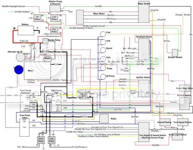
When you get a chance take a look at this electrical layout and see what you think. I drafted this plan up and it wouldn't hurt to have a second set of eyes to look at and comment. I am in the process of this rewire and upgrade. Using OE switches and aftermarket gauges.
http://s131.photobucket.com/albums/p...ialPlanV22.jpg
Let me know if you can't blow this up...I will try and get a larger verison posted.
Moderator
Joined: Jan 2001
Posts: 56,999
Likes: 2,746
From: Virginia
I am assuming the red wire from the bat + is the large wire? This will not have a fusible link in it like in your diagram. The fusible link will be in series with the black/orange wires going to the alternator.
What is the pwr relay for that is right above the starter relay, and is hooked into the red/blue wire from the neutral safety switch and goes to the headlights?
What is the pwr relay for that is right above the starter relay, and is hooked into the red/blue wire from the neutral safety switch and goes to the headlights?
Thread Starter
|
Fleet Mechanic
Joined: Aug 2005
Posts: 1,462
Likes: 74
From: Hartford, AL
The fused will be on the black/orange going to the alternator. I was running out of space. I knew where it would be, just didn't want to forget it. The power relay going to the headlight relays is ignition hot. I will not be able to turn on the lights until motor is started, but if I cut the truck off the headlights will go off..even if I leave the switch on....unless you have a better way to run this? I appreciate your time. A second set of eyes are always good.
Moderator
Joined: Jan 2001
Posts: 56,999
Likes: 2,746
From: Virginia
That line (red/blue to the starter relay) will only be hot when the key is sprung over to start. So you will only have headlights when the starter is turning.
Trending Topics
Thread Starter
|
Fleet Mechanic
Joined: Aug 2005
Posts: 1,462
Likes: 74
From: Hartford, AL
...ahh..that's right...I will change to trigger with accessories. good catch, thanks. I haven't wired that part yet, so easy fix.
FTE Stories
Ford Trucks for Ford Truck Enthusiasts

Top 10 Fords at 2026 Carlisle Ford Nationals
Joe Kucinski
3 Best / 3 Worst Parts of Modern Ford Ownership
Brett Foote
10 Amazing Upgrades That Solve Common Ford Truck Owner Headaches
Pouria Savadkouei
Every 2026 Ford Engine Explained
Brett Foote
10 Ugly Ford Trucks That We Still Kinda Love
Joe Kucinski
10 Things Every Truck Owner NEEDS (2026 Edition)
Michael S. Palmer
Rezvani's Latest Post-Apocalyptic Monster Is a Ford F-150 Raptor Underneath
Verdad Gallardo
Top 10 Most Expensive Ford Trucks Ever Sold on Bring a Trailer
Joe Kucinski
2027 Ford Super Duty Buyer's Guide (Every Model, Engine, & Package)
Brett FooteThread Starter
|
Fleet Mechanic
Joined: Aug 2005
Posts: 1,462
Likes: 74
From: Hartford, AL
Thought about that...in 73 it was on the same circuit as the windshield washer. I will cut the orng/ylw wire at the back of the washer switch, cap end and then move orange/ylw to the switched fuse panel. Didn't thing about the brake light switch. I would cut the red coming out of the hazard flasher, cap off, and then move the red to hot fused panel. Correct? Wouldn't that just leave the Hazard flasher on a circuit by itself? I was thinking the hazard/turn signal combo on a circuit was ok.
Moderator
Joined: Jan 2001
Posts: 56,999
Likes: 2,746
From: Virginia
Tying them all on one circuit would be fine. But your diagram doesn't show that. For example, the brake light switch is shown going into the hazard light flasher. Now that you explained what you are doing, it makes sense, but the diagram should show a line from the brake light switch, and line from the hazard switch, and a line from the turnsignal switch, all going to a dot or a splice, and then a line from that splice going to the fuse box.
From your description I think you would have been fine, it's just the diagram didn't show what you were doing.
From your description I think you would have been fine, it's just the diagram didn't show what you were doing.
Thread Starter
|
Fleet Mechanic
Joined: Aug 2005
Posts: 1,462
Likes: 74
From: Hartford, AL
I think I will just leave the haz/brake light circuit as is (I made a mistake in above post and said hazard/turnsignal circuit)...it was wired like that from the factory. The red/wht is the power for the circuit and is coming from the hot fuse panel to the hazard flasher. The red wire comes out of a plug from the hazard flasher and then goes to the brakelight switch. The red/black comes off the brake light switch and goes to the steering column connector. The turnsignal switch is currently on a different circuit, but the same as the windshield wiper...again as the factory wired. Do you still think I should move it (the orange/yellow that is to 12v switched fuse panel) or keep as is...with the windshield washer circuit?

Thread
Thread Starter
Forum
Replies
Last Post
quakerj
1980 - 1986 Bullnose F100, F150 & Larger F-Series Trucks
12
Oct 13, 2019 12:04 PM
FordTruckfan89
1987 - 1996 F150 & Larger F-Series Trucks
13
Apr 3, 2014 08:33 PM