
Main Light Switch

Thread Starter
|
Cargo Master


Joined: Sep 2004
Posts: 2,757
Likes: 138
From: Alberta Canada
Main Light Switch
I dont' have a scanner, but if you can visualize the pinouts on my 50 F1 light switch. It has five terminals in total, looking from front, three on left and two on right. If you numbered the left three, back to front: 1, 2, 3 and right ones 4, 5; here is what I meter out. With switch off: terminals 1 and 4 are common. With switch in park light position: 1, 2 and 4 are common, with switch full on: 4 and 2 are common. Confused yet ? 3 and 5 are also common when light sw full on. My manual shows six terminal switch for 51: but here's what I figure: power feeds #5 from ignition switch via starter relay through current circuit breaker. # 3 goes to dimmer switch power terminal. Power from voltage circuit breaker feeds #2. park lights are fed from #1. Instrument lights are fed from #4. How am I doing ? 
Tom
Tom


Post Fiend
Joined: May 2008
Posts: 7,641
Likes: 21
From: Poway, Ca.
Hi Tip,
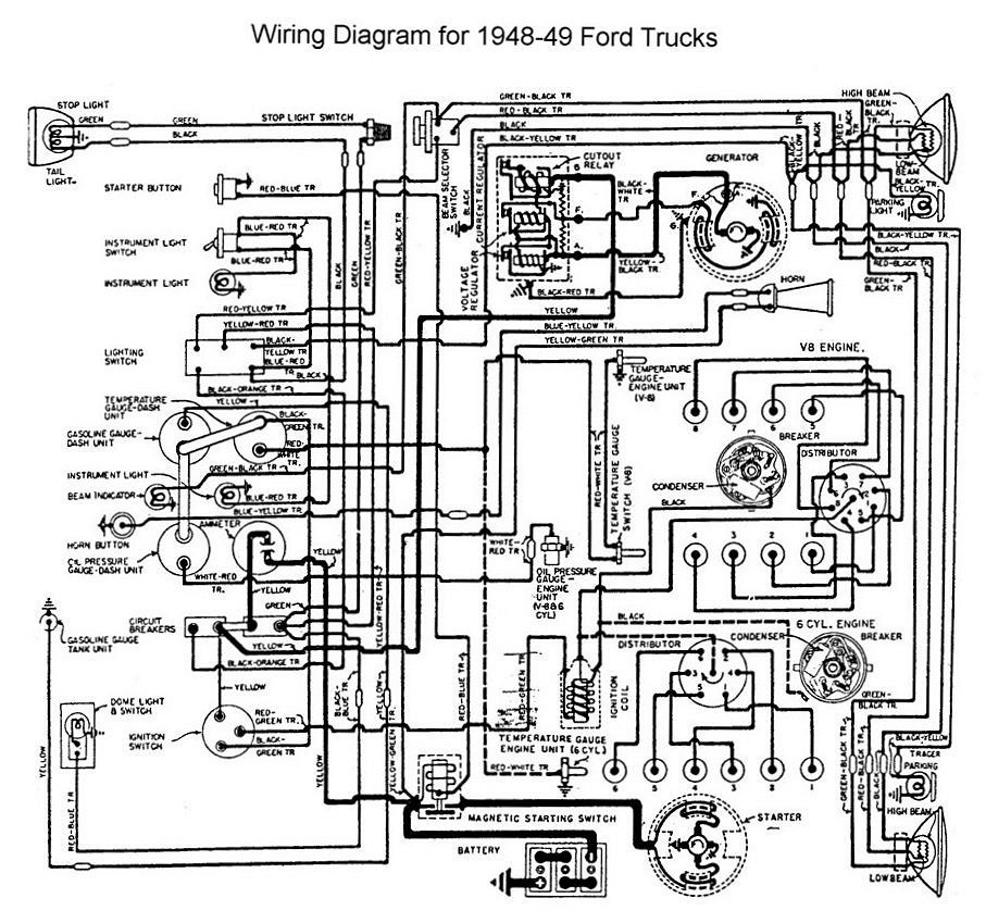
See if this helps. If you need any other diagrams look in my #1 gallery.

"Hot Bus" is your power source. My lights are powered off a fuse panel (bus) that is hot all the time (ie not switched on with the ingnition switch).
In the light switch diagram, the connection from the Right "R" terminal up and across to post on the left the interior lights rheostat (on the front of the switch that eventually flows from left to right to the instrument lights) is a hard metal shunt connecting those two points.
If you have an earlier type switch that required a separate toggle switch to turn on the instrument lights you will not have the rheostat on the headlight switch, and the hard shunt would be replaced by a wire connecting that "R" post to the separate toggle switch then going on to the actual instrument lights themselves.
The complete lighting diagram is in the gallery as well.
Good Luck,
Julie
See if this helps. If you need any other diagrams look in my #1 gallery.
"Hot Bus" is your power source. My lights are powered off a fuse panel (bus) that is hot all the time (ie not switched on with the ingnition switch).
In the light switch diagram, the connection from the Right "R" terminal up and across to post on the left the interior lights rheostat (on the front of the switch that eventually flows from left to right to the instrument lights) is a hard metal shunt connecting those two points.
If you have an earlier type switch that required a separate toggle switch to turn on the instrument lights you will not have the rheostat on the headlight switch, and the hard shunt would be replaced by a wire connecting that "R" post to the separate toggle switch then going on to the actual instrument lights themselves.
The complete lighting diagram is in the gallery as well.
Good Luck,
Julie

Thread
Thread Starter
Forum
Replies
Last Post
TRENT310
1999 - 2016 Super Duty
13
Oct 26, 2014 02:46 AM


