When you click on links to various merchants on this site and make a purchase, this can result in this site earning a commission. Affiliate programs and affiliations include, but are not limited to, the eBay Partner Network.
I have a new to me 93 f250, it's got the 460 and AC climate control. It was a farm truck that sat for a few years unused so now that i bought I'm finding small problems left and right. Current issue is that the temp is stuck on cold. First world problems i know. But I'm in montana and even though this has been a uncharacteristically warm winter I'd like to be able to not freeze. According to Google it's a cable controlling that blend door but i don't know where it runs or where to buy a new one. I'm used to the 80-86 trucks so stuff is just different enough to confuse me. While I'm making a post any advice for these truck's quirks would be welcome.
Look under the dash and rotate the **** while holding the cables. You should feel one vibrate or someway to tell which. Then follow it to the end of the cable, and move that thingy the opposite way it is now
I can't say for a fact that Google is wrong, but I would believe a thing its AI says. All of my '90 and '91 trucks have worked off vacuum, and I don't know why they would go back to cables. The blend door actuators were bad for stripping gears in the ones that I have had. I would check it out and look for mouse nests, since it was a farm truck.
I'm used to the 80-86 trucks so stuff is just different enough to confuse me.
The blend door is exactly the same.
Originally Posted by rwfid
I can't say for a fact that Google is wrong, but I would believe a thing its AI says. All of my '90 and '91 trucks have worked off vacuum, and I don't know why they would go back to cables. The blend door actuators were bad for stripping gears in the ones that I have had. I would check it out and look for mouse nests, since it was a farm truck.
I can. It has a cable. Your ‘90 and ‘91 were one of a kind. My ‘87, ‘89 and ‘94 all have a cable for the blend door.
Originally Posted by Hit Man X
Should be able to see the blend door actuator behind the glove box, the pin to the thing failed on my 92 I can snap a pic in a bit
Of course verify coolant actually is flowing through that heater core!
^^this^^ Open/ remove the glove box then watch the cable as you move the temp from hot to cold and back.
Good point. I wouldn’t be surprised if the core was clogged or at least restricted.
Remove the glove box, you will see the blend door cable.
There is a clip, black plastic hold down that had broke on mine. So it sounded and felt like the cable was moving, but the cable wasn't actually attached to the lever to move the door.
Ok, awesome I'll pop that glove box out today. I'm pretty sure there's sufficient coolant flow, both heater lines got hot to the touch. The **** doesn't travel crazy smooth so maybe I'll luck out and just need a new *** set. I found it interesting that there is to coolant flow valve on this truck maybe that's something they only did for the new body style super duties
My 84 is non AC so the "blend" door is out in the engine bay. And every bullnose I've seen has the same placement but they were probably dealer AC maybe the factory AC is different
Okay, I popped out the glove box and the cable in its attachment looked fine. I couldn't get it to move by hand though. So I took out the control set and I found that the **** for the temp controls had split so it was just spinning around the actual metal rod. Even grabbing it with pliers, It was very hard to get the rod to spin. so I separated the cable and it's stiff but it's movable. But the little gear set is still incredibly tight even with no actual load. So I think I need a new control head
^AIR CONDITIONING - LOW OR NO HEAT/AIR CONDITIONING - HIGH EFFORT TO TURN TEMPERATURE CONTROL **** - VEHICLES BUILT THROUGH 2/27/95
^AIR CONDITIONING/HEATER - HIGH EFFORT TO TURN TEMPERATURE CONTROL **** - POOR TEMPERATURE MODULATION - LOW OR NO HEAT/COOLING - VEHICLES BUILT THROUGH 2/27/95
^HEATER - LOW OR NO HEAT/AIR CONDITIONING - HIGH EFFORT TO TURN TEMPERATURE CONTROL **** - POOR TEMPERATURE MODULATION - VEHICLES BUILT THROUGH 2/27/95
ISSUE: The temperature control **** may be difficult to turn on some vehicles. There may also be a low or no heat/cooling condition accompanied by poor temperature modulation. This may be caused by the single cable temperature door operating system being used.
ACTION: Replace the A/C Temperature Control Cable Assembly with a new pull/pull cable design. The new design cable will provide improved control of the temperature door. Refer to the following Diagnostic and Replacement Procedures for details.
DIAGNOSTIC PROCEDURE
1.If the vehicle exhibits high effort turning the temperature control **** or poor temperature modulation, a new cable must be installed. Refer to the Replacement Procedure listed in this article. For a low or no heat/cooling concern, continue on with the Diagnostic Procedure.
2.Check vehicle's coolant for the correct level, concentration and operating temperature with the thermostat open. If a concern is found in one (1) of these areas, refer to the appropriate Service Manual for repair procedures. The repairs must be done before proceeding.
3.Verify proper A/C system charge and operation. Repair as necessary.
4.If the concern still exists, perform the Cable Adjustment procedure listed in the appropriate F-Series/8ronco Service Manual, Section 12.
5.If the concern still exists, replace the temperature door cable. Refer to the following Replacement Procedure for details.
REPLACEMENT PROCEDURE
REMOVAL
NOTE: REFER TO THE APPROPRIATE SERVICE MANUAL, SECTION 12, FOR EACH INDIVIDUAL COMPONENT REMOVAL AND INSTALLATION LISTED IN THIS PROCEDURE.
1.Remove glove compartment and module assembly, if present.
2.Detach cable from plenum using Tool D91T-18532-A. Remove and discard cable.
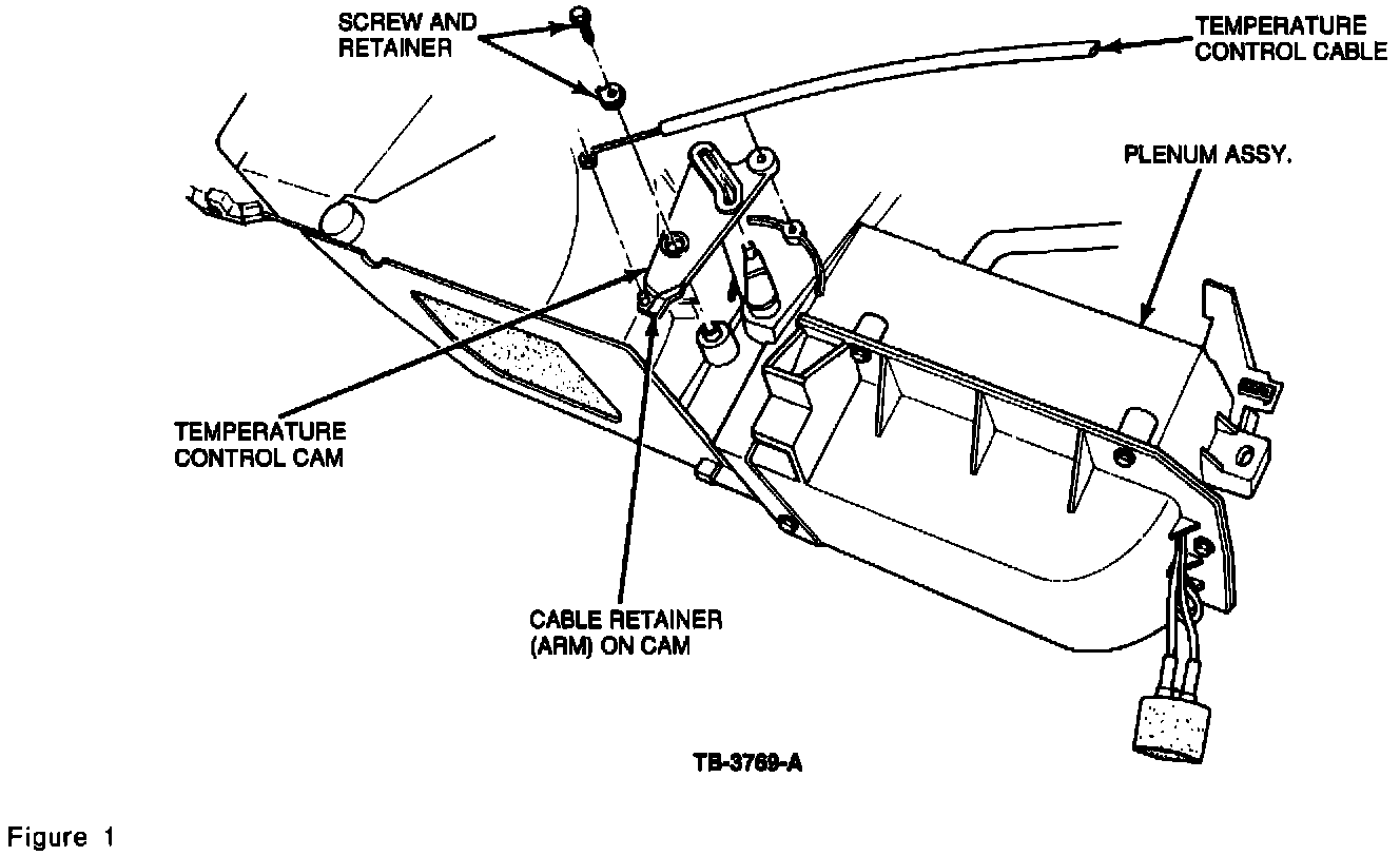
3.At the cable bracket on the plenum heater core cover, cut away the bracket using a hacksaw blade or similar tool. Refer to Figure 1.
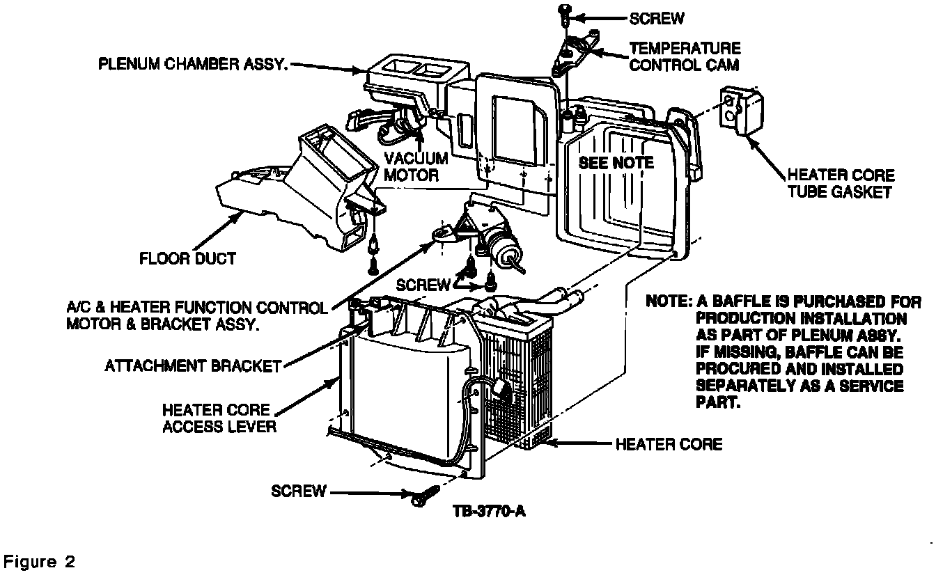
4.Remove the 5/16" headed screw from the top of the cam. Discard the cam and screw with spring clip. Refer to Figure 2.
5.At cam post, add post extension and secure with the new screw, torquing the screw to 1.7 N.m (15 lb.in). Refer to Figure 1.
6.Remove the upper left screw securing the plenum heater core cover and install the A/C plenum chamber support bracket between the ribs to the right side of the bracket which was cut off. Make sure the hole from the previously removed screw is lined up with the hole in the plenum chamber support bracket. Refer to Figure 1.
INSTALLATION
1.At the plenum chamber, move the temperature door arm to the "full warm" position (counterclockwise) and be sure it remains there throughout the installation procedure. Refer to Figure 1.
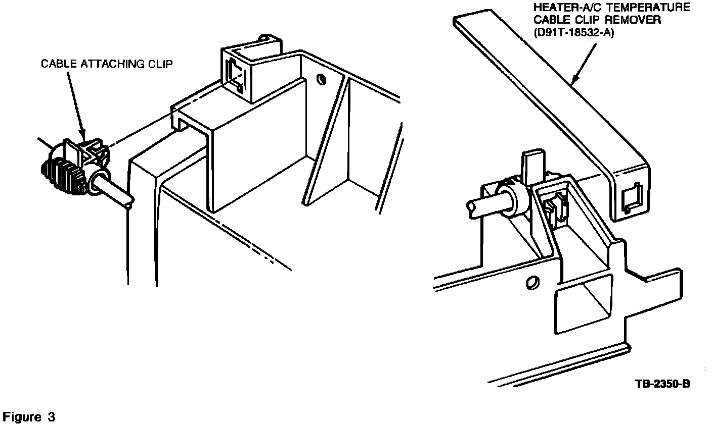
2.At the small end of the cable (control head), remove the temperature control bracket from the cable by releasing the three (3) snaps using Tool T94P-18532-A or a thin blade screwdriver to allow the cable to be pushed back through the instrument panel toward the control head. Refer to Figure 3.
3.Be sure the new pull/pull cable is in the full warm position. Check the molded-in arrow at the control head portion of the cable. Normally the cable is shipped in the "full warm" position.
4.At the plenum, position the cam end of the cable over the post. Make sure the temperature door arm can move into the slot of the cam and push down until the cam is engaged on the post. An audible click can be heard. If it is necessary to remove the cam cable head, use moderate finger pressure on the plastic tab at the top of the cam cable head, moving it back so the cam may be pulled out off the post. Refer to Figure 1.
5.Place the twin cables in the center slots of the A/C plenum chamber support bracket. If adjustment is needed later, the cables can be moved to the other adjacent slots. Refer to Figure 1.
6.Route new cable through the instrument panel following the same path as the old cable.
7.Check the new temperature control bracket to be sure it is in the "full warm" position. The tab should be in the slot in the bracket.
8.Push the temperature control bracket onto the control assembly and turn it to catch under the retaining tab. Secure with the new screw previously saved. Refer to Figure 3.
9.Place the **** on the temperature control.
10.Push the cable head onto the temperature control bracket (make sure gear pilot centering hole is lined up correctly) until the three (3) lock into position (you should hear a click of three (3) tabs). Refer to Figure 3.
12.Swiftly rotate temperature control **** to each extreme (cool-warm) and listen for the sound of the temperature door closing in both directions. If no audible close is heard, move the cable into different slots at the A/C plenum chamber support bracket covered in Step 4 of the Installation Procedure until there is an audible close in each direction.
13.Bring vehicle to operating temperature and verify proper heating and cooling by measuring the temperature of the discharge air at the outlets.
14.At A/C plenum chamber support bracket, secure cable to bracket with a tie strap to keep cable in place.
Obtain an Authorized Modifications Decal and list the date, dealer number, and summary of modifications performed. Select a prominent place adjacent to the Vehicle Emission Control Information Decal suitable for installing the Authorized Modifications Decal. Clean the area, install the decal, and cover it with a clear plastic decal shield.
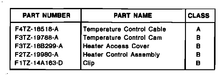
The Temperature Control Cable Kit (F5TZ-19988-CA) consists of:
Okay, I popped out the glove box and the cable in its attachment looked fine. I couldn't get it to move by hand though. So I took out the control set and I found that the **** for the temp controls had split so it was just spinning around the actual metal rod. Even grabbing it with pliers, It was very hard to get the rod to spin. so I separated the cable and it's stiff but it's movable. But the little gear set is still incredibly tight even with no actual load. So I think I need a new control head
Article No. 94-20-16
10/05/94
HEATER - LOW/NO HEAT WHEN TEMPERATURE **** IS SET AT FULL HEAT
LIGHT TRUCK: 1992-94 BRONCO, F-150-350 SERIES
ISSUE: Some vehicles may exhibit a low or no heat condition when the temperature **** is set to the full heat position. This may be caused by the temperature door cable not closing the temperature door fully.
ACTION: Adjust the existing cable to obtain full door closure. If the cable cannot be adjusted sufficiently to obtain full door closure, replace the temperature control cable. Refer to the following for repair procedures.
DIAGNOSTIC PROCEDURE
1.With a low/no heat condition, diagnosis should always begin with a check of the vehicle's coolant to be sure it is at the proper level, concentration and operating temperature with the thermostat open. If it is below specification, it should be corrected first.
2.Bring the vehicle to normal operating temperature.
a.On 1994 F-Series/Bronco: If low/no heat condition still exists, replace the temperature door control cable. For proper procedures, refer to the Service Procedure which follows.
b.On 1992-93 F-Series/Bronco: If low/no heat condition still exists, perform the control cable adjustment procedure as outlined in the Service Procedure which follows.
c.On 1992-93 F-Series/Bronco: If low/no heat condition still exists, disconnect the cable at the plenum and "wire" the door shut in the full warm position. With the engine still running, set the blower speed on "High" and place the mode selector on "Floor". Check for proper temperature and discharge air volume at the floor duct. If the low/no heat condition still exists and the coolant temperature is still in specifications, the concern could be blockage in the duct work or plenum, air leakage which chills off the air after it goes through the heater core, or possibly a defective plenum. Further diagnosis is required.
d.If wiring the door shut in the full heat position resolves the issue, the problem is most likely in the cable and a new cable should be installed. For proper procedures, refer to Service Procedure which follows.
SERVICE PROCEDURE
ADJUSTMENT PROCEDURE
1.Open the glove box to gain access to the adjustment clip.
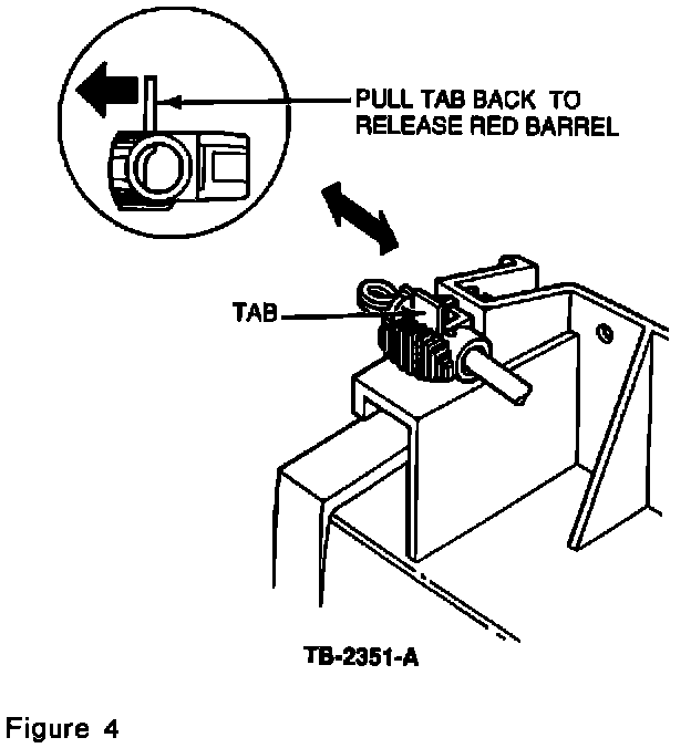
2.Pull back on the white tab on the adjustment as shown in Figure 4.
3.With the tab held back, move the barrel that travels through the clip in the direction required to obtain the proper door seating. Move the barrel one notch and verify that the door seats in each direction of travel.
NOTE: DO NOT MOVE THE BARREL MORE THAN TWO (2) NOTCHES FROM THE CENTER POSITION IN EITHER DIRECTION. MOVING THE BARREL MORE THAN TWO (2) NOTCHES MAY RESULT IN BARREL DETACHMENT FROM THE CLIP DURING LATER OPERATION OF THE TEMPERATURE CONTROL.
4.On 1992 vehicles, follow Steps 1, 2 and 3. However, in Step 3, if more than two (2) notches of travel are required, check the cable and cam for binding. If there is no binding present, replace the temperature control cable (F4TZ-18518-A), the temperature control cam (F3TZ-19788-A) and the heater access cover (F3TZ-18B299-A).
5.After attaching the cable and clip, make adjustments to the clip and verify that the temperature door closes at both ends of travel.
6.On 1993 vehicles, follow Steps 1, 2 and 3. If in Step 3, more than two (2) notches of travel are required, check the temperature control cam for binding. Cam binding can be checked by detaching the cable from the cam and actuating the cam by hand. The cam should move freely. If it is binding, adjust it to eliminate the binding. Reattach the cable and verify that the temperature door closes at both ends of its travel. If the temperature door does not close properly, replace the temperature control cable using (F4TZ-18518-A), adjust if necessary and verify that the door closes properly. If the door still does not close properly, the problem is most likely in the control assembly.
a.Continue by removing the control assembly. Detach the cable from the control assembly.
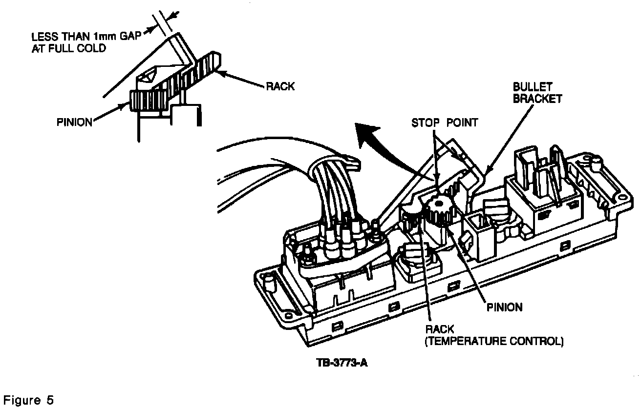
b.Check the travel of the rack when the temperature **** is rotated to the full cold position. The notch in the rack should stop at the bullet connector bracket when rotated to cold. Refer to Figure 5. If it does not come within 1 mm or touch the bracket, replace the control assembly (F2TZ-19980-A).
c.Reattach the cable and verify that the door closes at both ends of its travel.
7.On 1994 vehicles, verify that the temperature door closes at both ends of its travel. If the door does not close properly, replace the temperature control cable (F4TZ-18518-A).
a.Adjust the cable if necessary and verify that the door operates properly.
CABLE REMOVAL
NOTE: THE ADJUSTMENT CLIP IS ATTACHED TO A MOLDED-IN BRACKET LOCATED IN THE UPPER LEFT HAND AREA OF THE HEATER CORE ACCESS COVER. THE CLIP IS RETAINED BY TWO (2) TABS. THE HEATER-A/C TEMPERATURE CABLE CLIP REMOVER (D91T-18532-A, OR EQUIVALENT) IS REQUIRED TO DEPRESS THE LOCKING TABS IN ORDER TO ALLOW FOR REMOVAL FROM THE ATTACHING BRACKET.
1.Open the glove box door to gain access to the adjustment clip.
2.Position the removal tool over the bracket and clip as shown in Figure 3.
3.Align the opening in the removal tool with the retaining tabs which project through the bracket and pull back firmly (when properly aligned against the bracket, the tool handle will be horizontal but angled slightly downward). This will depress the locking tab but not disengage the clip from the bracket.
4.While maintaining the pull on the tool, pull the clip away from the bracket with the free hand.
5.Examine the adjustment clip for damage during removal. If one (1) or both tabs are broken or no longer spread away from the body of the clip, replace the clip (F1TZ-14A163-D).
6.Disengage the cable wire from the temperature door cam pin. Refer to Figure 1.
7.Refer to the appropriate Service Manual to remove the A/C Heater Control Assembly.
8.Disengage the cable connector and wire from the temperature door cam pin.
9.If the temperature door control cam is being replaced, it should be removed at this time. Refer to Figure 2.
10.If the heater core access cover is being replaced, it should be removed at this time. Refer to Figure 2.
CABLE INSTALLATION
1.Attach the new temperature door control cam (F3TZ-19788-A) if it is being replaced. DO NOT OVER TORQUE. Minimum torque is 0.7 N-m (6 in.lb.) and maximum torque is 1.7 N-m (15 in.lb.). Check for binding or too much movement effort and adjust if necessary.
2.Install the heater core access cover (F3TZ-18B299-A) if it is being replaced.
3.Install the A/C-Heater Control Assembly if it is being replaced. Refer to the appropriate Service Manual for installation procedures.
4.On the adjustment clip at the cable end, move the barrel so the red insert is on "center" and the red does not show out from either end. Further adjustment is not normally required, but can be made after installation, if necessary.
5.Attach the cable to the control assembly if not already attached in Step 3.
6.Attach the wire coil end to the temperature control cam. Be sure the cable is under the cable retainer. Refer to Figure 1.
7.Align the adjustment clip with the opening in the molded-in bracket as shown in Figure 3.
8.Push the clip firmly into place and ensure that both tabs hold the clip to the bracket (an audible click should be heard on engagement). Pull firmly on the clip to verify proper retention of the clip.
9.Rotate the temperature control to make sure the temperature door closes at both ends.
This Hennessey Takes the Expedition Tremor's Off-Roading Capability to the Next Level
Slideshow: The VelociRaptor Expedition gains a lift, upgraded suspension, Brembo brakes, and trail-ready equipment while retaining the stock 440-horsepower EcoBoost V6.
Rezvani's Latest Post-Apocalyptic Monster Is a Ford F-150 Raptor Underneath
Slideshow: Called the Fortress, the 850-horsepower pickup combines Raptor underpinnings with military-inspired features, survival equipment, and a starting price of $285,000.