


duraspark 2 wiring

Post Fiend
Joined: Feb 2008
Posts: 5,831
Likes: 121
From: St Albert, Alberta
1: The OP did not state if the coil connector was off or on. But if it had been OFF it would had had 12 volt in both run and start, I thought this would have been obvious with your high degree of knowledge.
2: Fair enough, but it is still information gained from a single voltage reading so I added it to the list.
3: You are just total wrong on this one, I can't even throw you a bone. The 7.45 volt reading in RUN indicates current flow which can only happen if the DS2 module is power ON. If ... while reading 7.45 volts on the coil, you unplug the DS2 power connector the voltage reading will jump to 12 volts. Again... I thought this would have been obvious with your high degree of knowledge.
4: The DS2 module was passing current, so it was power ON in the RUN position. I and sorry this is something you don't understand.
5: The info was given in post 16, you replied in post 17. Also you can tell by the 7.45 voltage reading.
6: Sorry, but you are missing the big picture on this one. 4.55 volts are being dropped across the coil + the DS2 module + the negitive side wiring. This is a normal voltage drop. But to be fair The OP can repeat the test, getting voltage reading on both sides of the coil, so then we will know what the voltage drop is downstream of the coil. But it runs in START so it is an unlike to see an issue here.
Overall, I don't think you have a good understanding of the circuit. Something as simple as... current flow through a resistor causes a voltage drop... seems hard for you to understand.
I have read a lot of your posts and I think you have a lot of knowledge. It would be helpful if you could share it without sharing your attitude.
Jim
Oh Man you do not give up do ya
1. If it was the coil connector OFF it would STILL show 6-8 In run and 12V in run. As you check Coil voltage from Coil Pos to ground or is that what the OP did Oh wait we don't know... Again no clue.
3: You are just total wrong on this one, I can't even throw you a bone. The 7.45 volt reading in RUN indicates current flow which can only happen if the DS2 module is power ON. If ... while reading 7.45 volts on the coil, you unplug the DS2 power connector the voltage reading will jump to 12 volts. Again... I thought this would have been obvious with your high degree of knowledge.
3. Oh Brother this goes to show how little you know.. The Coil can have power EVEN IF module has none in run. For that the Module picks up power off the SAME circuit as the ballast resistor BEFORE the ballast resistor. If that splice fails power to coil THROUGH the Ballast resistor to the coil with NO power to the Module.
Furthermore Unplugging the module has NO effect on power to the coil. As the Module DOES NOT supply power to the coil the ignition switch does. Unplugging the module will NOT affect the voltage seen at the coil.
Additionally, In Motorcraft modules, the module is OFF meaning the ground is open until one trigger signal is sensed from the distributor. Or does not sense a trigger signal in X amount of time after being on.
This to prevent coil overheat in the even the ign switch is left in run with out the engine running. That for showing you really have no clue what you are talking about.
4: The DS2 module was passing current, so it was power ON in the RUN position. I and sorry this is something you don't understand.
If the module had power in run then the truck would run in RUN but it does not, but runs in Start ... So likely a diagnostic error, considering he is missing power to a bunch of other systems in run.
It has to be considered that there is a or multiple wiring faults NOT in the ignition circuit.causing the current issues the same base circuit POST ignition switch feeds multiple items in the truck.
So is Power in actually coming from the source it is supposed to or is being back fed ?
And again no idea where this reading was picked up from was it harness side ot module side. . Again why a step by step HAS to be followed. And don't just go tossing jumpers into stuff without having an idea .
5. The info was given in post 16, you replied in post 17. Also you can tell by the 7.45 voltage reading.
And again how was it done? Was the coil disconnected? Was the 35 year old radio suppressor capacitor that now has likely degraded from a capacitor to a resistor taken out of the circuit, Do tell... That is why I said. "Possibly but again not really confirmed how it was done"
6: Sorry, but you are missing the big picture on this one. 4.55 volts are being dropped across the coil + the DS2 module + the negitive side wiring. This is a normal voltage drop. But to be fair The OP can repeat the test, getting voltage reading on both sides of the coil, so then we will know what the voltage drop is downstream of the coil. But it runs in START so it is an unlike to see an issue here.
Again NO voltage is dropped across the module The module is JUST a switch. There is NO volt drop downstream of the coil, downstream of the is ground when triggered by the module . You clearly do not have an understanding of how the system works. There is NO ground for the coil when the engine is NOT running the Module defaults to OPEN, Open switch NO ground. If there is ground between the Coil and the module with the engine off then there is wiring fault in the system. The system ground goes between the Dist and the Module NO TEST has been performed to verify it's integrity. So no we do not know what kind of shape the ground it in. Again it is quite apparent you have a very flawed understanding of how the system works. And are NOT contributing to this in any sort of positive manner. Simple as that.
Your understanding of how the system works is flawed and being flawed you are NOT providing constructive feedback.
Post Fiend
Joined: Feb 2008
Posts: 5,831
Likes: 121
From: St Albert, Alberta
Ya well some of us have no time for those that really have no clue but somehow think they do cause they read how to do it.

Thread Starter
|
New User
Joined: Oct 2020
Posts: 16
Likes: 0
hi again ,well the hotwire and jumper at icm did not resolve my issue the truck still died when key is released leading me to believe i have a power distribution problem rather than an ignition problem
Moderator


Joined: Jan 2001
Posts: 56,984
Likes: 2,738
From: Virginia

You hot wired to the battery + the coil, and both the red and the white wires at the ICM. all at the same time, and it still stopped when you turned the key off? All points critical to the ignition should be hooked directly to the battery. Not sure how it still cut off.
Cargo Master


Joined: Mar 2008
Posts: 2,569
Likes: 207
From: Washington
False statement are mark in red below.
1. If it was the coil connector OFF it would STILL show 6-8 In run and 12V in run.
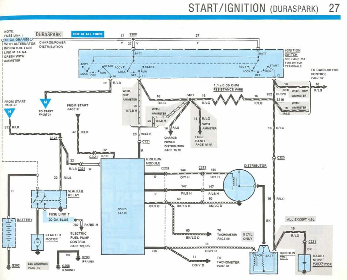
The above statement is false. It takes current flow to create the voltage drop across the resistor wire. Once again this something you are struggling with, if you understood this basic concept it would really help. With the connector off (no current flow) its just 12 volts for both run and start. You should really run out to your truck and test this before posting false information.
The Coil can have power EVEN IF module has none in run.
The above is a correct statement. But I was talking about current flow though the coil. Applied voltage is not the same as current flow.
To get current flow you need a completed circuit.
Unplugging the module will NOT affect the voltage seen at the coil.
The above is a false statement. With the key ON in the run position, the voltage at the coil is reduced due to current flow through the resistor wire. Unplugging the 2 wire power connector or the 4 wire connector on the DS2 module will open the circuit and stop current flow, thus you will see 12 volts at the coil not 7.45 volts.
Additionally, In Motorcraft modules, the module is OFF meaning the ground is open until one trigger signal is sensed from the distributor. Or does not sense a trigger signal in X amount of time after being on.
This to prevent coil overheat in the even the ign switch is left in run with out the engine running. That for showing you really have no clue what you are talking about.
The above is a false statement. Please see the ETVM. Or this link Ignition - Gary's Garagemahal (the Bullnose bible)
On pages 23-01-4 - 23-01-5 Its very clear... "In the Run position, primary circuit current flows... snip"
Again NO voltage is dropped across the module The module is JUST a switch. There is NO volt drop downstream of the coil, downstream of the is ground when triggered by the module .
The above statement is false. The ETVM list a voltage drop across the module, it around 1 volt - give or take. Internally the DS2 module uses a power switching transistor. To forward bias the transistor would require .7 volts.
"you are NOT providing constructive feedback."
I am not trying to post constructive feedback. I am trying to get you to stop posting false information on this forum.
A lot of people come here to try learn stuff, post false info just makes this forum useless.
So post a reference from the ETVM showing you are correct. I bet you cant. But you can delete your posts with false info.
Jim
1. If it was the coil connector OFF it would STILL show 6-8 In run and 12V in run.
The above statement is false. It takes current flow to create the voltage drop across the resistor wire. Once again this something you are struggling with, if you understood this basic concept it would really help. With the connector off (no current flow) its just 12 volts for both run and start. You should really run out to your truck and test this before posting false information.
The Coil can have power EVEN IF module has none in run.
The above is a correct statement. But I was talking about current flow though the coil. Applied voltage is not the same as current flow.
To get current flow you need a completed circuit.
Unplugging the module will NOT affect the voltage seen at the coil.
The above is a false statement. With the key ON in the run position, the voltage at the coil is reduced due to current flow through the resistor wire. Unplugging the 2 wire power connector or the 4 wire connector on the DS2 module will open the circuit and stop current flow, thus you will see 12 volts at the coil not 7.45 volts.
Additionally, In Motorcraft modules, the module is OFF meaning the ground is open until one trigger signal is sensed from the distributor. Or does not sense a trigger signal in X amount of time after being on.
This to prevent coil overheat in the even the ign switch is left in run with out the engine running. That for showing you really have no clue what you are talking about.
The above is a false statement. Please see the ETVM. Or this link Ignition - Gary's Garagemahal (the Bullnose bible)
On pages 23-01-4 - 23-01-5 Its very clear... "In the Run position, primary circuit current flows... snip"
Again NO voltage is dropped across the module The module is JUST a switch. There is NO volt drop downstream of the coil, downstream of the is ground when triggered by the module .
The above statement is false. The ETVM list a voltage drop across the module, it around 1 volt - give or take. Internally the DS2 module uses a power switching transistor. To forward bias the transistor would require .7 volts.
"you are NOT providing constructive feedback."
I am not trying to post constructive feedback. I am trying to get you to stop posting false information on this forum.
A lot of people come here to try learn stuff, post false info just makes this forum useless.
So post a reference from the ETVM showing you are correct. I bet you cant. But you can delete your posts with false info.
Jim
Post Fiend
Joined: Feb 2008
Posts: 5,831
Likes: 121
From: St Albert, Alberta
False statement are mark in red below.
The above statement is false. It takes current flow to create the voltage drop across the resistor wire. Once again this something you are struggling with, if you understood this basic concept it would really help. With the connector off (no current flow) its just 12 volts for both run and start. You should really run out to your truck and test this before posting false information.
The above statement is false. It takes current flow to create the voltage drop across the resistor wire. Once again this something you are struggling with, if you understood this basic concept it would really help. With the connector off (no current flow) its just 12 volts for both run and start. You should really run out to your truck and test this before posting false information.
What do you think the meter uses to read the resistance of a resistor? magic pixie farts?
The METER applies current across the circuit in the Ω setting to measure the resistance. Do you think the resistance of the resistor changes once you apply system voltage and current to it ? Better inform the IEEE of this stunning breakthrough....

When reading Voltage the meter applies resistance across the circuit to read the voltage if you introduce resistance in a completed circuit you induce current flow and inturn can read the voltage.
Apparently, your grasp of electrical theory is absolutely non-existent as proven by the above.
The above is a false statement. With the key ON in the run position, the voltage at the coil is reduced due to current flow through the resistor wire. Unplugging the 2 wire power connector or the 4 wire connector on the DS2 module will open the circuit and stop current flow, thus you will see 12 volts at the coil not 7.45 volts.
Once again you seem to think that the meter uses magic pixie farts to read voltage The Coil has voltage EVEN when the ICM is unplugged as SOON as meter is connected that voltage can be read WITHOUT going through the coil and it will read between 6-8V.
Again you have NO CLUE what you are talking about.
The above is a false statement. Please see the ETVM. Or this link Ignition - Gary's Garagemahal (the Bullnose bible)
On pages 23-01-4 - 23-01-5 Its very clear... "In the Run position, primary circuit current flows... snip"
On pages 23-01-4 - 23-01-5 Its very clear... "In the Run position, primary circuit current flows... snip"
That is the description of the operation and NOTHING MORE it does not describe HOW IT DOES IT as it is not relevant to doing the diagnostics to system check. This sort of information is included in Dealer training manuals. NOT workshop manuals. You really did not think that the workshop manual was all the info techs got did ya ? Guess that is the difference between actually knowing and thinking you know..
Furhermore I already told you the DS II and DS I goes to an idle setting as soon as it powered up with the switching MOSFET in the module open, as soon as a signal is sensed from ONE pulse of the pick up in the dist the module starts triggering the switching MOSFET. Additionally, if the module does NOT sense a signal from the dist in X amount of time the switching MOSFET goes open. I already told you this is done to protect the coil from overheating and in addition to keep the ICM's switching MOSFET from overheating, in the event that the vehicle is left in run WITHOUT the engine actually running. The SAME timing circuit used for triggering the coil is used to do this..
Apparently, this concert is too complicated for you to understand...
And again right there is the difference between actually knowing and having to read something to think you know...
")
"you are NOT providing constructive feedback."
I am not trying to post constructive feedback. I am trying to get you to stop posting false information on this forum.
A lot of people come here to try learn stuff, post false info just makes this forum useless.
So post a reference from the ETVM showing you are correct. I bet you cant. But you can delete your posts with false info.
You have thoroughly demonstrated that you have NO clue what you are talking about. Besides not understanding basic electrical theory you are posting NO constructive feedback and do NOT have the knowledge or even the most basic understanding of the fundametals of the system to even use the dummy manual know what is false or not. So congrats on your display of complete and utter ignorance.
Post Fiend
Joined: Feb 2008
Posts: 5,831
Likes: 121
From: St Albert, Alberta
Again if you want this resolved there are steps that need to be followed..
FTE Stories
Ford Trucks for Ford Truck Enthusiasts

10 Things Every Truck Owner NEEDS (2026 Edition)
Michael S. Palmer
Rezvani's Latest Post-Apocalyptic Monster Is a Ford F-150 Raptor Underneath
Verdad Gallardo
Top 10 Most Expensive Ford Trucks Ever Sold on Bring a Trailer
Joe Kucinski
2027 Ford Super Duty Buyer's Guide (Every Model, Engine, & Package)
Brett Foote
Top 10 Ford Truck Tragedies
Joe Kucinski
AEV FXL Super Duty - the Super Duty Raptor Ford Doesn't Make
Brett Foote
Lobo Vs Lobo: Proof the F-150 Lobo Should Be Even Lower!
Michael S. Palmer
Ford's 2001 Explorer Sportsman Concept Looks For a New Home
Verdad Gallardo
10 Best Ford Truck Engines We Miss the Most!
Joe KucinskiModerator
Joined: Jan 2001
Posts: 56,984
Likes: 2,738
From: Virginia
P.S. Most Fords that had the electric pumps in the tanks had 460's. But according to the diagrams, there were some 5.8 equipped vehicles that did have the electric pump system also.
Thread Starter
|
New User
Joined: Oct 2020
Posts: 16
Likes: 0
i am still left to wonder why the white wire is hot at the harness side of the icm if i can find a decent wiring diagram perhaps the best step is to replace all the wires from power under dash thru the entire start/run circuit???
Post Fiend
Joined: Feb 2008
Posts: 5,831
Likes: 121
From: St Albert, Alberta
Again if you want this resolved there are steps that need to be followed, which you do not seem to be interested in doing .. So hey if you wanna replace all the wring due to what is likely one bad splice, all the power to ya....
Moderator
Joined: Jan 2001
Posts: 56,984
Likes: 2,738
From: Virginia

Thread
Thread Starter
Forum
Replies
Last Post
ESCBuckets
6.7L Power Stroke Diesel
4
Jan 24, 2016 04:55 PM