Helical LSD into an Aerostar
#1
 05-30-2018, 01:56 PM

Helical LSD into an Aerostar
Write-up with pics.
Install procedure only, not a review of products, brands or results.
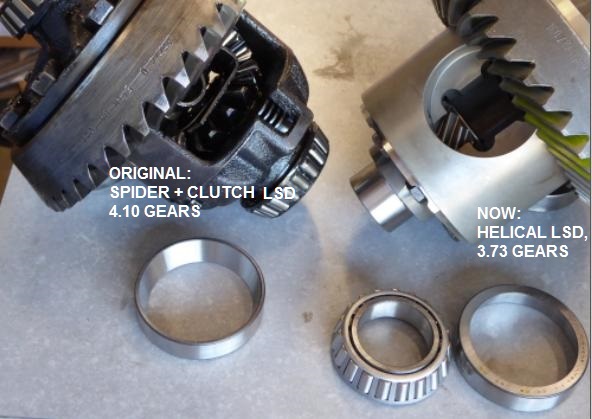
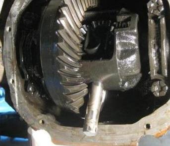
The particular vehicle ('89 short) updated here has put in a quarter-million miles, ie "the moon distance", and it is assumed that the LSD, an Eddie Bower trim-level feature using clutch-type technology, is "out of spec", ie no longer even functioning. The original bearings in the housing have suffered the same moon trek.
Rather than merely servicing the original clutch pack, it was decided to swap out the stock differential for a new unit employing helical-style limit slip technology, known under various trademarked names. At this time, the only supplier left for the legacy Ford 7.5 is Eaton, from their road going TrueTrac line (PN 912A316). The comparable unit for the Ford 8.8 28-spline is Eaton part number 912A562 and is not shown here. Fyi, if one were to somehow migrate to the Explorer axle with the 8.8 31-spl, a world of suppliers then opens up.
Concurrent with this diff retrofit, the gear set is migrated from 4.10 to 3.73. This is part of a bigger mission to improve fuel economy. Regardless of the numerical change, it is a huge benefit to bring in a new gear set rather than reusing the original as this eliminates the need to disassemble the original components, a non-trival task than might result in damage anyway. The original gear set also has also gone the moon distance and looks it, so we are happy to get the old parts out of here.
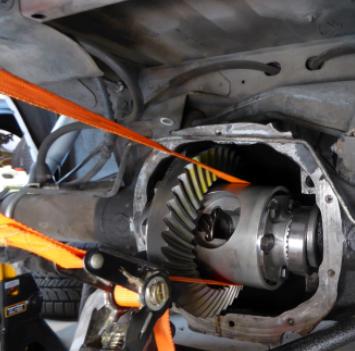
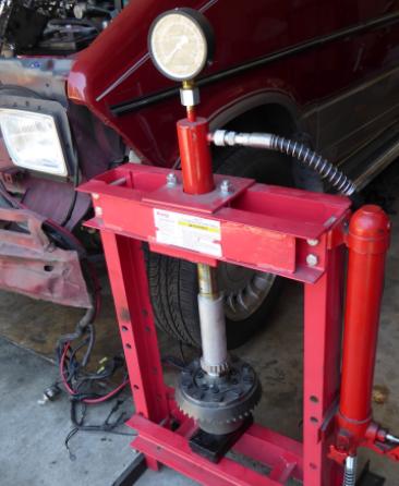
This swap is done with the axle still in the vehicle. On the plus side, this means we not spending time on that effort and are not having to manhandle and store a 200 lb axle, possibly damaging it. On the minus side, this means we are performing the diff operations in limited space with limited lighting. In either case we are under a jacked vehicle getting dirty and banged up. If you are not in good shape, don't get personally involved.
Other rear axle threads by RojoStar...
1) Axle maintenance
2) Brake overhaul
3) Sway bar install
4) Suspension bushings
Products installed
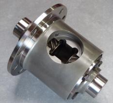
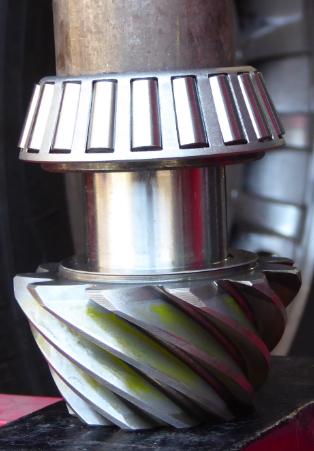
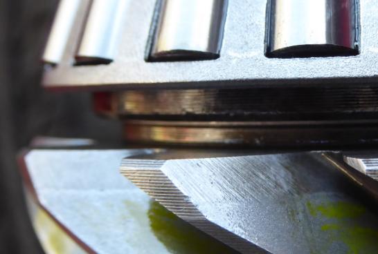
Helical gear style LSD, TrueTrac 912A316 for the Ford 7.5, by Eaton Corporation.
Shown here without the c-clip axle spacer.
Came with a pamphlet titled "Eaton Differential Owner's Manual" and states that...
- the instructions be used as "reference only". If available, the factory service manual should be referenced for complete details and specifications
- The installation be performed by a qualified technician.
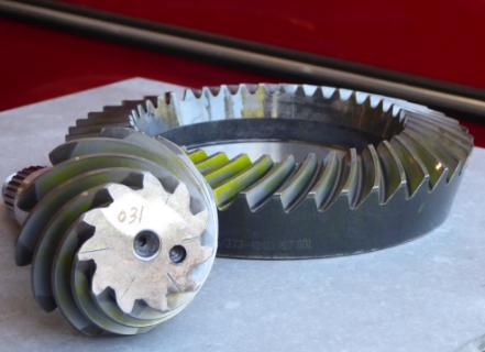
Gear set, 3.73, ZG F7.5-373, Standard Gear brand.
Came with a pamphlet titled "Kit Installation Instructions".
Overhaul Kit, YKF7.5, Yukon Gear & Axle brand.
Came with a pamphlet titled "Kit Installation Instructions", and since this is the same content supplied in the gear set above, we might assume a common ownership between the Yukon and Standard Gear brands.
A word about documentation
The products come with pamphlets, also available on line. In all 3 cases they were written in standard english with no spelling flaws or grammatical flaws detected. The caveats paraphrased from Eaton (above) should be taken seriously, as they are not merely legal CYA, and they neatly sum up the limitations of kit supplied documentation.
If we could only use one word to describe the overall documentation resources it would be the word "vague". In order to do this project or any similar level of wrenching, you must bring with you a set of skills and knowledge that you will not gain from reading the material supplied in the kits. Moreover the supplied pamphlets are not application specific to any particular vehicle. Therefore the documents either generalize an operation or state they might what must be done but not reveal how to do it. Commonly one is told there are multiple design styles possible, but it is not revealed which one is actually used in your specific application.
On the other hand, the factory documentation supplies official details and specifications, like methods and bolt torque values. Look for the powertrain/drivetrain volume, not the body/chassis or electrical/vacuum volumes. "Unfortunately" the factory docs are an unabridged resource, covering much more than an individual project and not necessarily in an organized sequence.
Third-party documentation (ie Haynes et al) imo fail to provide sufficient details, and in one case, fails to even cover the differential assembly.
The intent of this here write-up is to bridge the gaps between the kit documentation and the factory documents while providing photos of actual parts, tools and methods in an organized sequence for the specific application of the Ford Aerostar with a 7.5 axle. Parts and pictures would be different for other applications such as the Aerostar 8.8 axle. Where appropriate, specific data are pulled from the factory and kit documentation.
- more -
Install procedure only, not a review of products, brands or results.
The particular vehicle ('89 short) updated here has put in a quarter-million miles, ie "the moon distance", and it is assumed that the LSD, an Eddie Bower trim-level feature using clutch-type technology, is "out of spec", ie no longer even functioning. The original bearings in the housing have suffered the same moon trek.
Rather than merely servicing the original clutch pack, it was decided to swap out the stock differential for a new unit employing helical-style limit slip technology, known under various trademarked names. At this time, the only supplier left for the legacy Ford 7.5 is Eaton, from their road going TrueTrac line (PN 912A316). The comparable unit for the Ford 8.8 28-spline is Eaton part number 912A562 and is not shown here. Fyi, if one were to somehow migrate to the Explorer axle with the 8.8 31-spl, a world of suppliers then opens up.
Concurrent with this diff retrofit, the gear set is migrated from 4.10 to 3.73. This is part of a bigger mission to improve fuel economy. Regardless of the numerical change, it is a huge benefit to bring in a new gear set rather than reusing the original as this eliminates the need to disassemble the original components, a non-trival task than might result in damage anyway. The original gear set also has also gone the moon distance and looks it, so we are happy to get the old parts out of here.
This swap is done with the axle still in the vehicle. On the plus side, this means we not spending time on that effort and are not having to manhandle and store a 200 lb axle, possibly damaging it. On the minus side, this means we are performing the diff operations in limited space with limited lighting. In either case we are under a jacked vehicle getting dirty and banged up. If you are not in good shape, don't get personally involved.
Other rear axle threads by RojoStar...
1) Axle maintenance
2) Brake overhaul
3) Sway bar install
4) Suspension bushings
Products installed
Helical gear style LSD, TrueTrac 912A316 for the Ford 7.5, by Eaton Corporation.
Shown here without the c-clip axle spacer.
Came with a pamphlet titled "Eaton Differential Owner's Manual" and states that...
- the instructions be used as "reference only". If available, the factory service manual should be referenced for complete details and specifications
- The installation be performed by a qualified technician.
Gear set, 3.73, ZG F7.5-373, Standard Gear brand.
Came with a pamphlet titled "Kit Installation Instructions".
Overhaul Kit, YKF7.5, Yukon Gear & Axle brand.
Came with a pamphlet titled "Kit Installation Instructions", and since this is the same content supplied in the gear set above, we might assume a common ownership between the Yukon and Standard Gear brands.
A word about documentation
The products come with pamphlets, also available on line. In all 3 cases they were written in standard english with no spelling flaws or grammatical flaws detected. The caveats paraphrased from Eaton (above) should be taken seriously, as they are not merely legal CYA, and they neatly sum up the limitations of kit supplied documentation.
If we could only use one word to describe the overall documentation resources it would be the word "vague". In order to do this project or any similar level of wrenching, you must bring with you a set of skills and knowledge that you will not gain from reading the material supplied in the kits. Moreover the supplied pamphlets are not application specific to any particular vehicle. Therefore the documents either generalize an operation or state they might what must be done but not reveal how to do it. Commonly one is told there are multiple design styles possible, but it is not revealed which one is actually used in your specific application.
On the other hand, the factory documentation supplies official details and specifications, like methods and bolt torque values. Look for the powertrain/drivetrain volume, not the body/chassis or electrical/vacuum volumes. "Unfortunately" the factory docs are an unabridged resource, covering much more than an individual project and not necessarily in an organized sequence.
Third-party documentation (ie Haynes et al) imo fail to provide sufficient details, and in one case, fails to even cover the differential assembly.
The intent of this here write-up is to bridge the gaps between the kit documentation and the factory documents while providing photos of actual parts, tools and methods in an organized sequence for the specific application of the Ford Aerostar with a 7.5 axle. Parts and pictures would be different for other applications such as the Aerostar 8.8 axle. Where appropriate, specific data are pulled from the factory and kit documentation.
- more -
The following users liked this post:
#2
05-30-2018, 02:02 PM
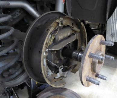
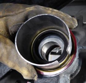
Site prep & removal of original
- Jack van, wheels off, brake drums off, strip lights strung, lookin' like sci-fi CGI.
- Check the fill hole plug. Removable? If not, decide on a plan B, possibly retrofitting a fill hole into the back cover.
- Remove the cover and drain the oil. Typically 4 quart pan required.
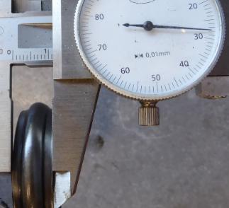
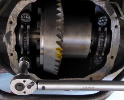
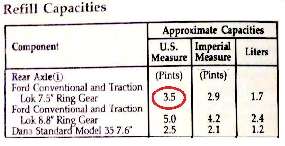
- At some point before removing the end caps and diff assembly from inside the housing, check the backlash on the ring gear, aka the amount it can rotate forward and backward when the pinion gear is locked. Although it is not essential to know the original value, we did this anyway to test out our measuring methods against a known working example. Since we are swapping the ring & pinion, we original lash numbers are no longer useful going forward, rather we reference back to factory specs.
First we immobilize the yoke with a long bar-clamp.
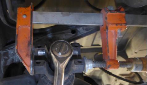
The dial indicator was affixed to the sway bar that conveniently floated right in front of the case at the proper distance. Lash is calc'd as the difference between two measurements, 1.008 - 0.094 = 0.014, within the spec window of 0.011 to 0.016.
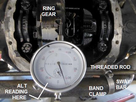
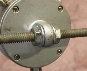
My threaded rod passes thru the eyelet on the back side.
- Start removing diff internals.
Remove the retaining bolt that holds the cross shaft in the differential.
- Remove the cross shaft
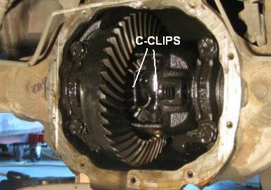
- Remove C clips. Hint: push the axles inboard slightly, to expose the C-clips.
- Remove the axle shafts. Some instructions warn of perils of resting the shaft on the end seals.
- Notes to self:
1) Restore the cross pin and retainer bolt, so they are not lost or interfer with procedures.
2) Measure ring gear lash before this point, epecially if retaining the original ring & pinion set.
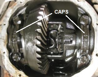
- Mark the bearing caps, iow's identify left v right and orientation up v down. Then remove them.
- Pull the differential assembly out of the housing. If this is not workable by hand, then try this method as discussed later during the install.
Wash out the housing. Look out for any debris.
- Remove the output/side shims and record the thickness.
- With yoke still immobilized, remove pinion nut. Careful, the pinion assembly is free to fall out the back at this time.
- Remove front seal. Typically get started with a sturdy box cutter blade and progress to screw driver tips.
- At this point the front bearing and washer are free to fall out.
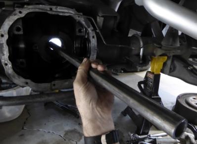
- "Tap out" the original pinion bearing races. In fact our largest punch was neither long nor sturdy enough.
Instead an 18 inch x 1 inch bar or thick-walled tube, motivated by a 2 lb hammer.
- more -
- Check the fill hole plug. Removable? If not, decide on a plan B, possibly retrofitting a fill hole into the back cover.
- Remove the cover and drain the oil. Typically 4 quart pan required.
- At some point before removing the end caps and diff assembly from inside the housing, check the backlash on the ring gear, aka the amount it can rotate forward and backward when the pinion gear is locked. Although it is not essential to know the original value, we did this anyway to test out our measuring methods against a known working example. Since we are swapping the ring & pinion, we original lash numbers are no longer useful going forward, rather we reference back to factory specs.
First we immobilize the yoke with a long bar-clamp.
The dial indicator was affixed to the sway bar that conveniently floated right in front of the case at the proper distance. Lash is calc'd as the difference between two measurements, 1.008 - 0.094 = 0.014, within the spec window of 0.011 to 0.016.
My threaded rod passes thru the eyelet on the back side.
- Start removing diff internals.
Remove the retaining bolt that holds the cross shaft in the differential.
- Remove the cross shaft
- Remove C clips. Hint: push the axles inboard slightly, to expose the C-clips.
- Remove the axle shafts. Some instructions warn of perils of resting the shaft on the end seals.
- Notes to self:
1) Restore the cross pin and retainer bolt, so they are not lost or interfer with procedures.
2) Measure ring gear lash before this point, epecially if retaining the original ring & pinion set.
- Mark the bearing caps, iow's identify left v right and orientation up v down. Then remove them.
- Pull the differential assembly out of the housing. If this is not workable by hand, then try this method as discussed later during the install.
Wash out the housing. Look out for any debris.
- Remove the output/side shims and record the thickness.
- With yoke still immobilized, remove pinion nut. Careful, the pinion assembly is free to fall out the back at this time.
- Remove front seal. Typically get started with a sturdy box cutter blade and progress to screw driver tips.
- At this point the front bearing and washer are free to fall out.
- "Tap out" the original pinion bearing races. In fact our largest punch was neither long nor sturdy enough.
Instead an 18 inch x 1 inch bar or thick-walled tube, motivated by a 2 lb hammer.
- more -
#3
05-30-2018, 02:10 PM
Installation of new
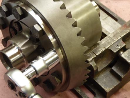
- "Tap in" the new pinion bearing races. Use the original races as the mandrel, coincidentally the same diameter. Front bearing shown, the tougher rear bearing not shown. When fully seated, a feeler gauge can not be (blindly) inserted between the race and housing. Not to worry, the torquing of the pinion nut will (probably) seat the race anyway.
- Prep the ring gear, diff assembly.
If retaining the ring & pinion set, remove the ring gear from the differential. This procedure is not shown here because we are not reusing the gear set or the LSD carrier.
Our ring mounting bolts have standard right-hand threads. Note any tone ring between ring gear and diff flange, and mark orientation.
Ring gear is typically pressed onto a pilot diameter of the diff. To remove the ring gear from the diff, a hydraulic press is preferred.
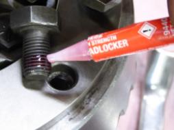
- Install ring gear on the new differential, preferrably with new bolts. To seat the gear, we spent approximately 10 minutes gradually turning the 10 mounting bolts while paying attention to alignment. The bolts did reach across to get started.
Apply locking compound such as Loctite 263 (high strength red) and torque the bolts to 60 ft-lbs.
Immobilizing the housing is problematic. This pic, we attempted on a low vise. Worked up to a minimal point, then we had to find another way.
Never clamp on the ring gear or bearing shoulders. Instead use the barrel area. Ideally some sort of torque reaction arm can be bolted on. Alternately a deep bench vise grabs the cylinder. In our project we had neither and ended up sandwiching the assembly between some very thick packing material and our foot. Just barely worked.
- Using the hydraulic press, install the side bearings onto the differential and ring assembly.
The press-in mandrel should be just slightly smaller than the bearing cage, so that mandrel only makes contact with the inner race. As the hubs will protrude beyond the seated bearing, its important to use a hollow tube mandrel rather than a solid round bar.
- Prep the pinion for install.
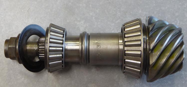
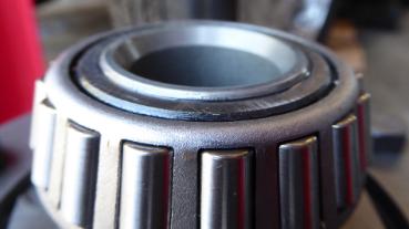
Select a pinion shim. Here we wanted to default to the original shim thickness. We had to eyeball this because we were not going to disassemble the original pinion assembly just to get at it. The shim selected from the overhaul kit measured approx 0.017 inch. Later we found the factory spec to be 0.025 and still later, after installing pinion, we found our selection to be quite adequate if not actually perfect.
Using the hydraulic press, the rear bearing's roller cage section is pressed onto the shaft, sandwiching our shim.
Ordinary pressure is around 1.5 tons. We know the bearing is seated fully when the pressure suddenly goes up.
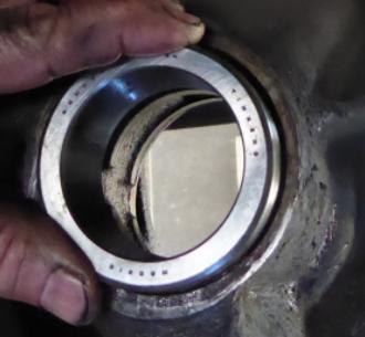
Load the crush sleeve.
Here we have a problem with the overhaul kit, because the sleeve(s) supplied are considerably wider than the original (shown).
Even if the kit sleeves are correct, experience on previous builds has also told me that crushing a sleeve takes much more force than is available while working by hand, without hydraulics, under a vehicle. Not only that but the spec for installation is not how much force is applied to the crush, but how much rotational drag results when the pinion nut is properly torqued down. So facing several ambiguities and risks, we default to reusing the original sleeve. Although we are warned against this move, it seemed to work out just fine. Can't imagine the benefit to doing it "correctly".
Lube the pinion nut. If you don't, then before you finish torquing, you'll stop, reverse out the nut, then lube it, then continue what you were doing.
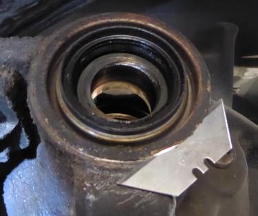
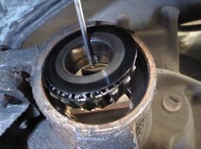
- Install the new front seal. This requires us to first insert/place the front bearing and washer.
The seal is thrusted at the bottom, not squished from the outer rim. We did not have an official tool and the bin of tubing sections did not yield an exact diameter.
Cutting a smaller diameter tube, it coincidentally expanded out to precisely what we needed.
A board or plate is then layed over the edge and the seal tapped home with 16 oz hammer.
We know the seal is seated if we can not casual slip a knife blade between the lip and housing.
- Reach around the housing, hold the pinion in place while the threaded end at the front is loaded up with yoke and nut. Wiggle the pinion around until satisfied that its finding the bore in the front bearing, so the bearing can be torque down onto the pinion shaft. Note the original bearing was much looser on the shaft, and showed signs of spinning the inside race rather than the roller bearings rolling on the race. So, we are happy with the new fitment.
- Immobilize the yoke. A bar clamp was ok to start but couldn't keep up with the load from pressing in the front bearing, had to be releaved by a monster pipe wrench, the type that weighs like ten pounds. There is no way this pipe wrench is going to loose this contest.
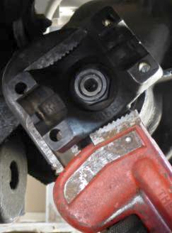
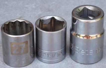
- Torque the pinion nut. 27mm socket, aka 1-1/16, std/shallow ok.
Fyi, I had this available from the Beta brand luxury collection but it was in a 3/4 drive which combines with a very serious 3/4 x 40" Valadium breaker, way overkill.
Instead we stick with a lowly 1/2 x 18" breaker and I can assume only that the force was reaching up to perhaps 150 ft-lbs. This was enough to move the front bearing down the pinion shaft and get it seated against the front race with a very smooth pinion rotation, no slop, no binding. Since we can't see the crush sleeve, there is no knowledge about its situation other than, in this case, we've put things back the way they were.
The specification is to achieve a rotational drag of 14 to 19 inch-lbs new. Note: inch. This is difficult to measure since it is not break away torque, but rather the torque while in motion.
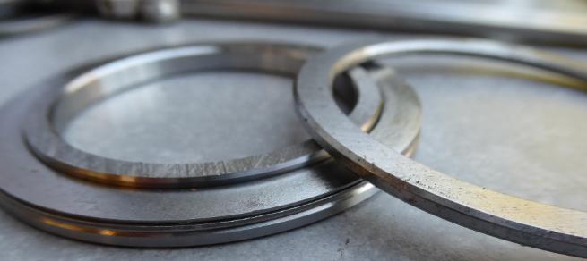
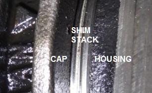
- Consider the side shim selection. A no-brainer starting point is the original thickness.
Whereas the original shimming was done using a solid rings, the overhaul kit has a system whereby a stack of several thin rings is sandwiched between a hubbed end and another thick end cap.
Starting with our default value, we assembly a stack to replicate the orignal thickness. However, this led to a "too tight" condition, resisting even a tap-in via wood block and hammer. To proceed further,we would have to own and use a case spreader. However, a casual twist of the gear set told me the drag had increased significantly. Although this would probably reduce over time, my instincts were to get back to where I had originally found the set up, which was a gear set that could be more easily tapped into place.
We were then challenged with the task of hauling the assembly back out. After 10 minutes of staring and over-thinking, we got out some hold down straps with a rachet mechanism, good to several hundred pounds.
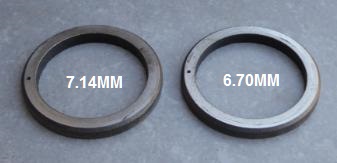
Equal amounts were "shaved" off of each side by swapping in alternate shims. Eventually we had reduced the total shimming by 0.52 mm below stock. Fyi: Left shim now at 6.80mm, right at 6.54.
- Install the end caps, noting original left/right and orientation and torque the cap bolts to spec, "whatever that might be". Not having a shop manual handy, I guessed 60 ftlbs to be appropriate. Someday soon when the shop manual is present, if I'm way off on the low side, I'll correct.
Note that the caps slightly cover the side shims, and because of the stack design, this is sufficient to retain the entire stack.
- more -
- Prep the ring gear, diff assembly.
If retaining the ring & pinion set, remove the ring gear from the differential. This procedure is not shown here because we are not reusing the gear set or the LSD carrier.
Our ring mounting bolts have standard right-hand threads. Note any tone ring between ring gear and diff flange, and mark orientation.
Ring gear is typically pressed onto a pilot diameter of the diff. To remove the ring gear from the diff, a hydraulic press is preferred.
- Install ring gear on the new differential, preferrably with new bolts. To seat the gear, we spent approximately 10 minutes gradually turning the 10 mounting bolts while paying attention to alignment. The bolts did reach across to get started.
Apply locking compound such as Loctite 263 (high strength red) and torque the bolts to 60 ft-lbs.
Immobilizing the housing is problematic. This pic, we attempted on a low vise. Worked up to a minimal point, then we had to find another way.
Never clamp on the ring gear or bearing shoulders. Instead use the barrel area. Ideally some sort of torque reaction arm can be bolted on. Alternately a deep bench vise grabs the cylinder. In our project we had neither and ended up sandwiching the assembly between some very thick packing material and our foot. Just barely worked.
- Using the hydraulic press, install the side bearings onto the differential and ring assembly.
The press-in mandrel should be just slightly smaller than the bearing cage, so that mandrel only makes contact with the inner race. As the hubs will protrude beyond the seated bearing, its important to use a hollow tube mandrel rather than a solid round bar.
- Prep the pinion for install.
Select a pinion shim. Here we wanted to default to the original shim thickness. We had to eyeball this because we were not going to disassemble the original pinion assembly just to get at it. The shim selected from the overhaul kit measured approx 0.017 inch. Later we found the factory spec to be 0.025 and still later, after installing pinion, we found our selection to be quite adequate if not actually perfect.
Using the hydraulic press, the rear bearing's roller cage section is pressed onto the shaft, sandwiching our shim.
Ordinary pressure is around 1.5 tons. We know the bearing is seated fully when the pressure suddenly goes up.
Load the crush sleeve.
Here we have a problem with the overhaul kit, because the sleeve(s) supplied are considerably wider than the original (shown).
Even if the kit sleeves are correct, experience on previous builds has also told me that crushing a sleeve takes much more force than is available while working by hand, without hydraulics, under a vehicle. Not only that but the spec for installation is not how much force is applied to the crush, but how much rotational drag results when the pinion nut is properly torqued down. So facing several ambiguities and risks, we default to reusing the original sleeve. Although we are warned against this move, it seemed to work out just fine. Can't imagine the benefit to doing it "correctly".
Lube the pinion nut. If you don't, then before you finish torquing, you'll stop, reverse out the nut, then lube it, then continue what you were doing.
- Install the new front seal. This requires us to first insert/place the front bearing and washer.
The seal is thrusted at the bottom, not squished from the outer rim. We did not have an official tool and the bin of tubing sections did not yield an exact diameter.
Cutting a smaller diameter tube, it coincidentally expanded out to precisely what we needed.
A board or plate is then layed over the edge and the seal tapped home with 16 oz hammer.
We know the seal is seated if we can not casual slip a knife blade between the lip and housing.
- Reach around the housing, hold the pinion in place while the threaded end at the front is loaded up with yoke and nut. Wiggle the pinion around until satisfied that its finding the bore in the front bearing, so the bearing can be torque down onto the pinion shaft. Note the original bearing was much looser on the shaft, and showed signs of spinning the inside race rather than the roller bearings rolling on the race. So, we are happy with the new fitment.
- Immobilize the yoke. A bar clamp was ok to start but couldn't keep up with the load from pressing in the front bearing, had to be releaved by a monster pipe wrench, the type that weighs like ten pounds. There is no way this pipe wrench is going to loose this contest.
- Torque the pinion nut. 27mm socket, aka 1-1/16, std/shallow ok.
Fyi, I had this available from the Beta brand luxury collection but it was in a 3/4 drive which combines with a very serious 3/4 x 40" Valadium breaker, way overkill.
Instead we stick with a lowly 1/2 x 18" breaker and I can assume only that the force was reaching up to perhaps 150 ft-lbs. This was enough to move the front bearing down the pinion shaft and get it seated against the front race with a very smooth pinion rotation, no slop, no binding. Since we can't see the crush sleeve, there is no knowledge about its situation other than, in this case, we've put things back the way they were.
The specification is to achieve a rotational drag of 14 to 19 inch-lbs new. Note: inch. This is difficult to measure since it is not break away torque, but rather the torque while in motion.
- Consider the side shim selection. A no-brainer starting point is the original thickness.
Whereas the original shimming was done using a solid rings, the overhaul kit has a system whereby a stack of several thin rings is sandwiched between a hubbed end and another thick end cap.
Starting with our default value, we assembly a stack to replicate the orignal thickness. However, this led to a "too tight" condition, resisting even a tap-in via wood block and hammer. To proceed further,we would have to own and use a case spreader. However, a casual twist of the gear set told me the drag had increased significantly. Although this would probably reduce over time, my instincts were to get back to where I had originally found the set up, which was a gear set that could be more easily tapped into place.
We were then challenged with the task of hauling the assembly back out. After 10 minutes of staring and over-thinking, we got out some hold down straps with a rachet mechanism, good to several hundred pounds.
Equal amounts were "shaved" off of each side by swapping in alternate shims. Eventually we had reduced the total shimming by 0.52 mm below stock. Fyi: Left shim now at 6.80mm, right at 6.54.
- Install the end caps, noting original left/right and orientation and torque the cap bolts to spec, "whatever that might be". Not having a shop manual handy, I guessed 60 ftlbs to be appropriate. Someday soon when the shop manual is present, if I'm way off on the low side, I'll correct.
Note that the caps slightly cover the side shims, and because of the stack design, this is sufficient to retain the entire stack.
- more -
#4
05-30-2018, 02:13 PM
Measure the fitment
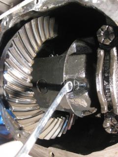
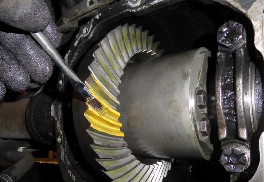
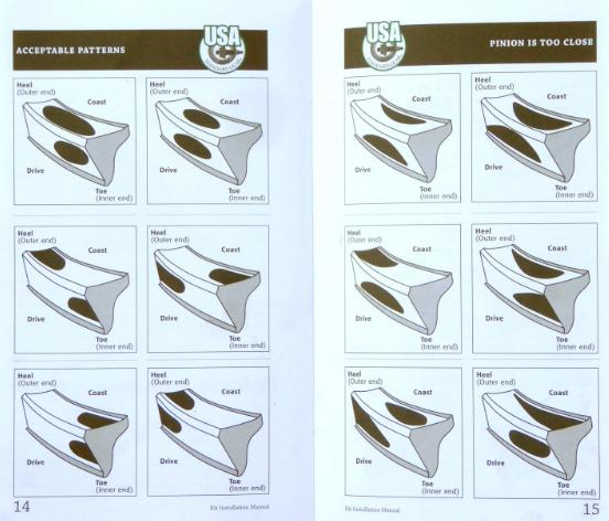
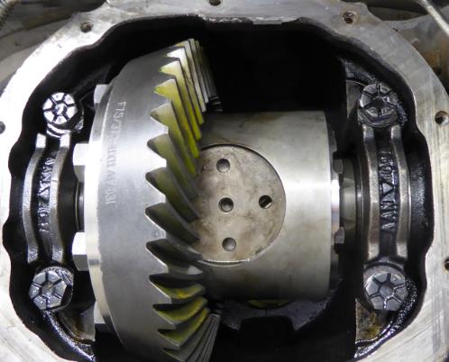
Apply marking compound, rotate the gear set, look at the contact pattern, compare against pictures in the instruction manual.
Use the brush to create solid monochrome.
Then twist the pinion (over the top towards the left-hand side of the vehicle, to simulate forward transmission).
Applying opposite drag on the ring to simulate a drive condition, or apply motivating force on the ring and drag on the pinion to simulate a coasting condition.
Note that this simulated drag is most convenient we can do while under the vehicle, but ultimately we would like to apply a preload drag of say 30 lb-ft while doing this measurement. Getting fancy on another project this was achieved by winding a strap around the assembly, then off to a pulley and weight. Similar deal on the pinion side.
Coast side pattern, at bottom.
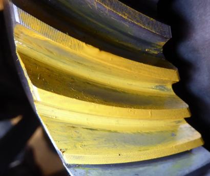
Drive side pattern.
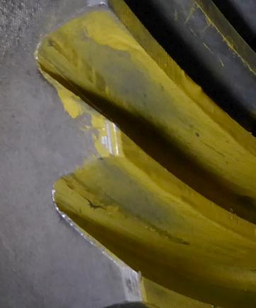
Check against the pattern library to determine if the pinion is too far rearward or forward.
In our case, non of the combinations of coast side and drive side matched our situation.
However after studying the library, it was concluded that the top consideration, whether coast or drive, is that the mesh pattern is centered on the face, top to bottom, iow's from ridge to trough, and be a complete or cropped oval. On the other hand the library examples seem not to care where along the axis, inboard to outboard, the oval is located. In our case, on the coast side we have almost a perfect oval, centered between ridge and trough, bias somewhat inward. On the drive side we have a truncated oval, centered between ridge and trough, cropped by the outside edge. This acheived on the first try, by eyeballing the original pinion shim thickness and duplicating it. That makes us very lucky. Otherwise we have to pull the pinion out, and strip the rear bearing off, to change the shim. All without breaking anything.
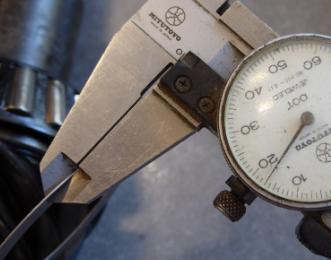
- Set up the dial indicator, measure the lash.
First measurement, x.x88"
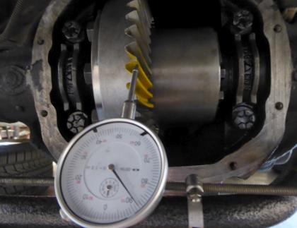
Shift ring gear, second measurement, x.x98".
Difference is 0.010. Spec is 0.011 to 0.016.
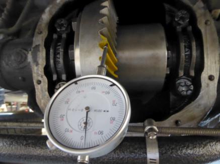
Iterate shims to acheive specified lash. To increase lash, move the ring gear left, farther from the pinion. When you have the backlash correct then the final step is to add about .003 to .005 to each side to make the fitment very tight, where the differential can not be pulled out by hand. Since our lash is just (tight) outside the specified window, we add a single .005 shim to the right side. This tightens the fitment and increases lash by .003.
Use the brush to create solid monochrome.
Then twist the pinion (over the top towards the left-hand side of the vehicle, to simulate forward transmission).
Applying opposite drag on the ring to simulate a drive condition, or apply motivating force on the ring and drag on the pinion to simulate a coasting condition.
Note that this simulated drag is most convenient we can do while under the vehicle, but ultimately we would like to apply a preload drag of say 30 lb-ft while doing this measurement. Getting fancy on another project this was achieved by winding a strap around the assembly, then off to a pulley and weight. Similar deal on the pinion side.
Coast side pattern, at bottom.
Drive side pattern.
Check against the pattern library to determine if the pinion is too far rearward or forward.
In our case, non of the combinations of coast side and drive side matched our situation.
However after studying the library, it was concluded that the top consideration, whether coast or drive, is that the mesh pattern is centered on the face, top to bottom, iow's from ridge to trough, and be a complete or cropped oval. On the other hand the library examples seem not to care where along the axis, inboard to outboard, the oval is located. In our case, on the coast side we have almost a perfect oval, centered between ridge and trough, bias somewhat inward. On the drive side we have a truncated oval, centered between ridge and trough, cropped by the outside edge. This acheived on the first try, by eyeballing the original pinion shim thickness and duplicating it. That makes us very lucky. Otherwise we have to pull the pinion out, and strip the rear bearing off, to change the shim. All without breaking anything.
- Set up the dial indicator, measure the lash.
First measurement, x.x88"
Shift ring gear, second measurement, x.x98".
Difference is 0.010. Spec is 0.011 to 0.016.
Iterate shims to acheive specified lash. To increase lash, move the ring gear left, farther from the pinion. When you have the backlash correct then the final step is to add about .003 to .005 to each side to make the fitment very tight, where the differential can not be pulled out by hand. Since our lash is just (tight) outside the specified window, we add a single .005 shim to the right side. This tightens the fitment and increases lash by .003.
#5
05-30-2018, 02:16 PM
Close up
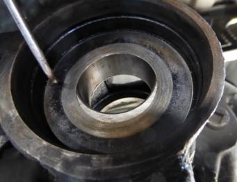
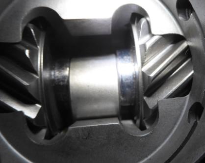
- Install axles, pushing them all the way inboard to reveal the groove that receives the C-clips. Note an o-ring also sits in this groove, its function is to retain the C-clip briefly during installation. Fyi, groove dia was 19mm.
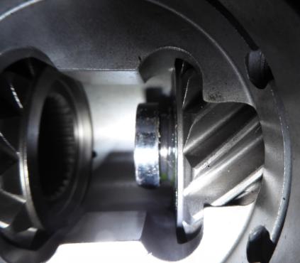
Fyi, these c-clips are all that keeps your shafts, with wheels, from flying out the ends of the rear axle.
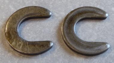
The axle is then pushed back to the outside, capturing the C-clip inside the differential canister.
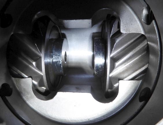
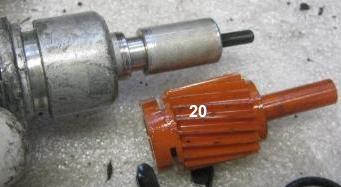
- The Eaton TrueTrac uses a different system than the factory for retaining the axles in their outboard position. While the factory method sends a cross pin thru the space between the axles, the TrueTrac uses a puck, this being then held in place a cover, the cover being held in place by an inside snap ring.
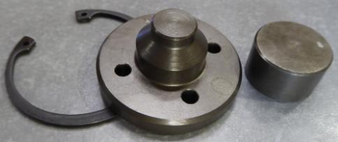
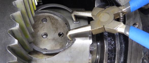
- Install spacer retainer
The spacer retainer is then held in place by a snap ring.
These pliers are an example of what won't work.
Too small (about 5-6 inches) with straight tip where we want bent tip.
A half-hour later, no progress.
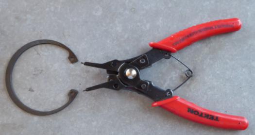
By contrast, the correct tool took a mere five seconds.
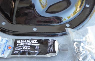
- Install diff housing cover. Because of chronic trouble with seepage (aka leaking), we are bringing in a new cover, this time in steel versus the original plastic and continuing the use of gasket maker rather than a rubberized paper gasket.
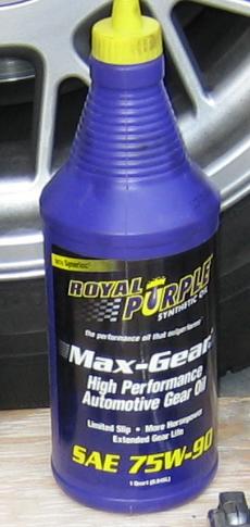
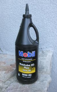
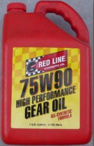
- Add 75 or 80W90 oil, either mineral or synthetic. Some people, in hot climates or towing, go to 75W140.
DO NOT add LSD slip additives as that is only applicable to clutch type technology. The change in slip would negatively alter the properties of a helical gear type by sending bias more towards an open type.
- There arises a problem with tagging, the gear change effectively creating a B4 spec axle and making a liar out of the door jamb tag.

The bigger problem is with the diff tag, where we would want to inform the future owner and mechanics as to the current gearing, but also scold against adding LSD modifiers.
Fyi, these c-clips are all that keeps your shafts, with wheels, from flying out the ends of the rear axle.
The axle is then pushed back to the outside, capturing the C-clip inside the differential canister.
- The Eaton TrueTrac uses a different system than the factory for retaining the axles in their outboard position. While the factory method sends a cross pin thru the space between the axles, the TrueTrac uses a puck, this being then held in place a cover, the cover being held in place by an inside snap ring.
- Install spacer retainer
The spacer retainer is then held in place by a snap ring.
These pliers are an example of what won't work.
Too small (about 5-6 inches) with straight tip where we want bent tip.
A half-hour later, no progress.
By contrast, the correct tool took a mere five seconds.
- Install diff housing cover. Because of chronic trouble with seepage (aka leaking), we are bringing in a new cover, this time in steel versus the original plastic and continuing the use of gasket maker rather than a rubberized paper gasket.
- Add 75 or 80W90 oil, either mineral or synthetic. Some people, in hot climates or towing, go to 75W140.
DO NOT add LSD slip additives as that is only applicable to clutch type technology. The change in slip would negatively alter the properties of a helical gear type by sending bias more towards an open type.
- There arises a problem with tagging, the gear change effectively creating a B4 spec axle and making a liar out of the door jamb tag.
The bigger problem is with the diff tag, where we would want to inform the future owner and mechanics as to the current gearing, but also scold against adding LSD modifiers.
#6
05-30-2018, 02:20 PM
Speed in gears
Because we have changed the gearing and the speed sensing on our Aero is upstream from these gears, our speedometer will now read incorrectly.
We will need to swap out the speedo drive gear found on the rear of the transmission.
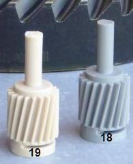
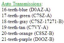
Ours originally had an an orange coded gear, with 20 teeth, and so the 10% change in R&P therefore prompts us to select a tan coded, with 18 teeth.
This will get us close, however the speedo had also been reporting about 3% lower than GPS, because of bigger than stock tires, and so we might drop down still further with a green coded 17 tooth.
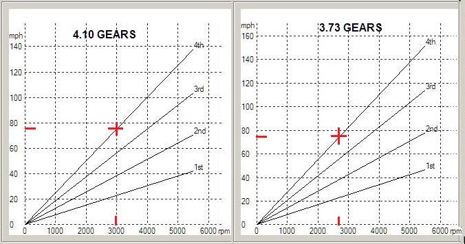
The migration of the gearing from 4.10 to 3.73 is part of an over all personality change, from street-sport to highway-cruiser. Cruising rpm drops from 3000 (@75mph) to 2730.
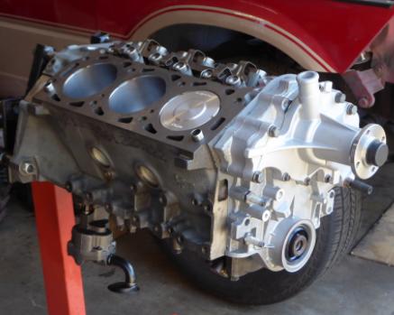
Concurrent with the gear set change, the 3L engine torque is boosted by roughly 15 lb-ft, via a swap out of the early engine (88-91) , for a new build featuring later technology, namely roller cams (92+), a higher compression ratio (2002+), and a custom controller.
Fuel economy rises from 18.5 (@65mph) to 21.5, increasing range by about 60 miles for a total with reserve now at about 410 miles.
We will need to swap out the speedo drive gear found on the rear of the transmission.
Ours originally had an an orange coded gear, with 20 teeth, and so the 10% change in R&P therefore prompts us to select a tan coded, with 18 teeth.
This will get us close, however the speedo had also been reporting about 3% lower than GPS, because of bigger than stock tires, and so we might drop down still further with a green coded 17 tooth.
The migration of the gearing from 4.10 to 3.73 is part of an over all personality change, from street-sport to highway-cruiser. Cruising rpm drops from 3000 (@75mph) to 2730.
Concurrent with the gear set change, the 3L engine torque is boosted by roughly 15 lb-ft, via a swap out of the early engine (88-91) , for a new build featuring later technology, namely roller cams (92+), a higher compression ratio (2002+), and a custom controller.
Fuel economy rises from 18.5 (@65mph) to 21.5, increasing range by about 60 miles for a total with reserve now at about 410 miles.
#7
05-30-2018, 03:35 PM
Trending Topics
#8
06-22-2018, 03:33 AM

Great write-up, and I finally understand the purpose of the case-spreader plates I got in a Rotunda tool set.
A question on the choice of TrueTrac. You mentioned this is the only option for the 7.5" differential. If all3 of the major makers, TrueTrac, Torsen, and Powertrax, made a worm or helical gear diff for the 7.5", which one would you choose?
I read that Ford used a Torsen for its 2012 Boss Mustang, and had some failures because of too much power from the engine. Torsen improved its metallurgy the following year, and their later diffs were able to hold up to the high power levels without damage. Of course, this would be for the 8.8" diff with 31 spline axles.
#9
06-22-2018, 09:38 AM
I'm no expert in this area, I'm more of a generalist. And its been at least a half year since I did the research and procurement.
- Just to nit, TrueTrac is somewhere half way between a brand and a catalog line. Eaton is the manufacturer. Similar holds for the others mentioned. Torsen is a trademark referring to helical LSD technology.
- Afaik, the question is moot because there was only one (stocked, helical) option left for the 7.5 and the alternative choice went NLA a couple years back.
- There are several LSD technologies. Clutch, hydraulic intelligent clutch, helical, off-road locking and variations on these. There are pluses-minuses to each. For instance, as road surface friction drops to zero (ie you are on ice), helical can fail to engage, ironically just when you need it most. The tricky work around is to (very lightly) apply brakes while also applying power. Clutch technology does better in these conditions.
- There is a helical product, Wavetrac, that claims to take care of this, and my MBZ community has installing that into the rwd 190E for snow and ice. Wavetrac is available in the Ford 8.8/31 c-clip and this was considered in conjunction with a rear axle retrofit. However I've move on from my "Built to tow" plans and the Explorer axle is still sitting here waiting for the scrap metal guy to come by.
- Eaton implies that their product is designed to break second, only after your axle shafts have given up.
- Read the internet long enough and you will find some alpha male claiming to have broken this or that. Be cognizant of the context and whether it applies to you. Typically these bad-*** stories are then propagated by others who wish to imply that they too are alpha males doing alpha male things. Out there on the internet: "I was competition drag racing, with slicks, with 540rwhp, AND my Wavetrac broke. Total garbage." Really?
#10
06-23-2018, 01:36 PM
Thanks for the explanations. I realize the only option for the 7.5 was the Truetrac, but I was theorizing which version would have been the best option. In practice, I doubt I any car I plan to upgrade with one of these would generate enough power to break them. So maybe I would go for the lowest price.
I know "Truetrac" is a brand name, like "Positraction"; they're both trade names belonging to Eaton. Yet, so many people use "Posi", or "Positraction" to generically refer to limited slip differentials. This is my peeve; If I go to a supermarket to buy "Kleenex", and get generic facial tissue, I can still blow my nose into it. But if I go to an auto parts store and ask for clutch packs for the "Posi" in my Ford, the store attendant may ask me what GM rear end I have in it.
The Torsen is a worm gear/worm wheel set up, while Truetrac and Powertrax are both helical gears. But they're all open diffs that rely on the angle of the teeth on the drive gear vs driven gear to provide torque transfer from one side to the other. But they can only multiply SOME torque, so if one side has no traction, it's stuck, like any open diff. I seem to recall some outfit made a version of the Torsen with a preload clutch to prevent the total loss of traction problem.
#15
09-23-2018, 01:35 PM
More torque
Finally got my Vulcanstein build posted over in the engine forum.
The engine update happened simultaneous with the gear change here in and is what allowed me to go from 4.10 to 3.73 and mount heavier wheels and still feel a bit livelier.
The engine update happened simultaneous with the gear change here in and is what allowed me to go from 4.10 to 3.73 and mount heavier wheels and still feel a bit livelier.