When you click on links to various merchants on this site and make a purchase, this can result in this site earning a commission. Affiliate programs and affiliations include, but are not limited to, the eBay Partner Network.
Bronco78IDI's 1978 Bronco IDI Turbo swap Fabrication (lots of detailed info & pics)
Hi there forum, usually I am not on this part of the forums much anymore as I have been performing more write-ups on the Pre-Powerstroke Diesel side for my IDI Diesel Swaps. So as you may or may not already be familiar but I have been working for quite a few years with IDI Diesel Swaps in 1967-1979 F-Trucks. I'm finding that there are quite a few folks asking alot of questions on how to swap an IDI into their 4x4 F-Truck Chassis on many of my threads so I am starting this write-up on a current swap of a quite unique 6.9L IDI that is being transplanted into Bronco78IDI's (Robert Bronco) 1978 Bronco Freewheeler. This thread will loosley cover how to build swap mounts in 4x4 Frames from 1967-79 (and some other Trucks aswell, these Trucks have the same Engine mounting Locations with some slight differences here and there as to Shock Tower and Coil Bucket locations ect.) But will motly follow later style Bronco (78-79) and F100-F150 Chassis (other models will need crossmember notching such as in Highboys and 77.5-79 F250 and 1979 F350s.). If you have questions please feel free to ask.
Details on Robert's build is available in two FTE threads I will link below:
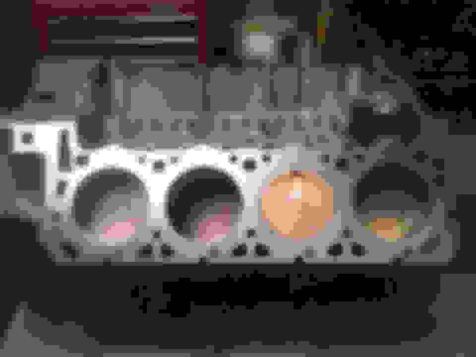
As of now the engine Mounts and Engine Swap modifications have been completed and we are currently working on stripping and coating the Chassis in preperation for the new Running Gear, the engine being used for the Motor Mount mock-up is a 1992 7.3L that will be in a later 1979 F350 Chassis-Cab build and is not Robert's 6.9L. Photos below of completed fab work and a small preview of Robert's unique 6.9L. I will start updating the build steps in the following few posts in this thread.
Before I start into Robert's Bronco I just want to throw out a few frame comparissons and measurments to show the width of the frames and measurments of the Engine Mount Tower locations of a few different Frames I have here at the shop just to show folks just how similar most of these 4x4 frames are as I have had some sceptics in the past. This wall also show a good example of how to notch a 77.5-79 F250 Frame Crossmember on a cut section of frame from my first IDI swap that was Cory Pratt's 1977.5 F250 (also a good example of how to not do motor mounts, those were not my creation)
1978 Ford Bronco (also same forward chassis as many F100-F150 4x4 Chassis)
Outer Frame Measurment at Motor Mounts (34")
Inner Frame Measurment at Motor Mounts (26")
1977.5 F250 (Cory Pratt's Former IDI Truck)
Outer Frame Measurment at Motor Mounts (34")
Inner Frame Measurment at Motor Mounts (26")
1977 Ford F250 Highboy
Outer Frame Measurment at Motor Mounts (34")
Inner Frame Measurment at Motor Mounts (26")
Last edited by Muddy74Ford; 12-13-2016 at 02:14 AM.
Reason: Loading photos, adding info
So to start off the first thing you should be doing to your Truck before thinking of building Motor Mount plates or swapping an IDI into your Truck should be to first Source your Engine and Transmission. The C6 and E4OD for the IDI shares mountings with the 1970s Trucks up until the Bellhousing patterns, the IDI shares upper Bellhousing bolt pattern with ford "Big Block Bell patterns, but the other 4 bolts will not match up and I do not suggest drilling thise holes to fit, source yourself a Diesel Transmission in this case and don't shortcut. The T19 4 speed that came in the IDI Trucks will share the same mountings as 70s Trucks, but will require use of the aluminum Adapter Center Housing from the T19 to a Married T-case setup, in a Divorced T-case application use a 2wd T19. Also another option is to use the Aluminum T19 Bellhousing from the IDI Truck on your current T18 or NP435 4 speed Transmission, in this build the original NP435 will be used. In a NP435 build I strongly suggest sending your Transmission input off for Cryogenic Treatment/Hardening if building for Perfomance. Any Manual Transmission will require converting to a Hydraulic Clutch which I will cover more later. The only other options are for a ZF5 or ZF6 transmissions, these have an extra degree of dufficulty as you will need to notch the front of a Married T-case Application and will need to drill the crossmember for the ZF5/6 mount, also all applications will need either a custom Transmission Floorpan Cover or a minimum of a 2" body Lift to clear the extra height of the Transmission, I will not be covering the ZF5/6 in this posting.
Now that all that has been covered the first step you should perform is to disassemble the front Clip of your truck (be prepared to soak some bolts overnight folks in the rust belt), you will need to strip your old motor down to just the Block, Heads, Crank Pulley, and water Pump (ect) the more the better. You will be measuring and leveling your frame and old Motor before removing it, it is important to level your frame to the ground and have your tires off the Ground for this, in the following photos you will notice I am using Adjustable Welding/Pipe Jacks (Airgas is a great place to pick these up) to lift and level all 4 corners of the bare frame (in this case) this will come into play later to properly level your new motor.
Lifting and leveling the Frame with Pipe Jacks:
Now obviously I do not have an Engine, Trans , or T-case mounted to my bare frame, so here it is all mounted back up:
Making sure that your engine is level is also very important, you also want to be sure to find the proper angle that your Engine is slanted from front-to-rear also with a Magnetic Protractor (available at most Hardware Stores) on a properly flat surface. This will be VERY important later as you will need to match this level and protractor angle with the new IDI Motor or you will run into driveline angle issue, you MUST match your old engine's angle and center.
Now is the perfect time to find your crank center and measure your frame at a marked location to center your IDI engine later, as you will see in the following photos I make corresponding marks on the Bronco and F100-F150 crossmembers that marks where the Crank Center is oriented in relation to the Crossmember. The IDI is a bit longer than the 351m that came in this Bronco, so my marks will come into play and make more sense after the IDI is mounted. At the point of measure the crank was centered at 15.5" from the passenger side of the fram, at the point of measure at the Crossmember the center is 15.25".
So now that the crank/engine center and angle has been found there is no need for the engine or Motor Mount towers to be in the Chassis anymore, if you have coil Buckets and Shock Mounts you will also want to remove these from the Frame at this point.
The first thing that needs to be done is to notch an small area of the Frame just inside the passenger side of the Frame, this area needs to be notched out before making your new Motor Mounts as it will be needed to clear the Starter Solenoid for the IDI, even if you are using the smaller replacment Starter or the aftermarket mini Starter you will still want to make this same notch in the Chassis.
This will be the end product of this cut, the notch will allow any Starter to clear the chassis, and I have a quick and simple way to mare these cuts with nothing but a paint pen, straight edge, a level, and a tape measure. To make these cuts I would highly suggest a Plasma torch and/or a Die Grinder.
Now, to cut this notch I have a great way to not only measure the correct location for this notch, but a fast and easy way to find the proper level for the vertical cut using the old Motor mount. Placing the passenger Mount back in it's old location on the chassis run a vertical mark on the frame on the firewall (back) side of the Mount, you can now remove the Mount and you should be le with, well... a vertical mark of which to measure out from. In my case I outlined the entire mount just for future reference.
After you have made that reference matk and removed the mount now you need yo make another reference mark that will mark your horizontal cut, from the top of the frame (the lower part of the framerail that is the half your mounts bolt to, not the highest point of the framerail in thus case) measure 3" down and mark the outer portion of the frame relief hole as shown below.
Now using the vertical Mount mark as a guide measure 2" forward on the frame, this will be the actual vertical cut for the notch, I tend to use a level as a straght edge to check the level and also mark the vertical cut because I'm OCD... but another good little tip for this cut is to clamp a piece of 2" angle iron to the chassis using a welder's clamp, just makes for a good guide for a plasma torch.
Very nice!
I have also seen others use mounts and a crossmember from a Diesel pickup and cut to fit. I looking at redoing mine since it was a hack job from previous owner.
I have also seen others use mounts and a crossmember from a Diesel pickup and cut to fit. I looking at redoing mine since it was a hack job from previous owner.
What trans are you using and what crossmember?
Yeah that works especially well for a 2wd swap, currently on my 1976 linked earlier i am developing a 2wd swap mount that is just a bolt-on, took a while to engineer it and had about 4 versions before the final mount. Not big on modufying the frame too much as I like to make it so other's can reverse what i have done and go back to gas ect. Also itxs just so easy to make proper mounts in a 4x4 frame.
The Transmission in this particular project is a strengthened NP435 original to the Bronco, keeping it mostly for the lower 1st gear as this will be a driver but also mainly a streetable Trail Toy.
the Original 4x4 crossmember is being used for now, eventually there will be either a 203 Splitter or a NWF "Black Box" splitter being put between the NP435 and the 205. If the Black Box is used I have a pretty good idea of a custom mount for the otiginal crossmember, with the 203 a custom member will be built.
Sadly with how much attention to detail is needed these write-ups take a little while with loading photos for the thread lol, alot more is coming.
Yeah that works especially well for a 2wd swap, currently on my 1976 linked earlier i am developing a 2wd swap mount that is just a bolt-on, took a while to engineer it and had about 4 versions before the final mount. Not big on modufying the frame too much as I like to make it so other's can reverse what i have done and go back to gas ect. Also itxs just so easy to make proper mounts in a 4x4 frame.
The Transmission in this particular project is a strengthened NP435 original to the Bronco, keeping it mostly for the lower 1st gear as this will be a driver but also mainly a streetable Trail Toy.
Sadly with how much attention to detail is needed these write-ups take a little while with loading photos for the thread lol, alot more is coming.
I hear ya. And I appreciate your post very much.
If you were me with the 7.3 zf 5 speed bw tranxcase, what front crossmember would you run and engine mounts?
I kinda out of room because the motor is to far back to firewall, and like I said before guy did a hack job. Think his only tool for this project was a torch
If you were me with the 7.3 zf 5 speed bw tranxcase, what front crossmember would you run and engine mounts?
I kinda out of room because the motor is to far back to firewall, and like I said before guy did a hack job. Think his only tool for this project was a torch
Inwould do the same mounts as I will be building here, but leave the Trans to crossmember as is and notch it in frontx then with the trans floating I would then suspend the motor and make the Engine Mounts, then after they are complete modify the crossmember to use the ZF5 studded Trans Mount. I can cover this more towards the end if you like, but here is a photo
To give you a rough idea without getting too far off track.
you are going to want to match the driveline angles that were stock, if you have a 205 still you can mate it to the ZF5, it honestly would be a great combo
Inwould do the same mounts as I will be building here, but leave the Trans to crossmember as is and notch it in frontx then with the trans floating I would then suspend the motor and make the Engine Mounts, then after they are complete modify the crossmember to use the ZF5 studded Trans Mount. I can cover this more towards the end if you like, but here is a photo
To give you a rough idea without getting too far off track.
OK great thanks for the tip. You wouldnt happen to have engine mount pics and where you got them. At this point I feel like ripping out the ones in there, and getting a crossmember from a 92 f250 with 7.3 engine mounts. Or do what you do and try and fix the "notching" this guy did
Will have to post pictures up tomorrow when it's not dark
I build my own using Factory components, this will be covered in a few posts.
please PM them as I am going to be using this posting for referencing this swap.
Now that everything is marked and set to cut I will be using the combination of Plasma Torch and Die Grinder, there will be a bolt sleeve/brace under where you are cutting, so just be prepared for it.
There will be a tack weld that will still keep the trimmed piece of Frame onto the Brace underneath it, to break it free just grab the steel with a pair of pliers and wiggle (yep, that's a technical term haha) back and forth until the weld breaks. After removal keep the trimmed piece off to the side for later use and using a straight edge mark and then cut the bolt brace square with the remaining portions of frame.
Make sure to true up the edge of the Framerail before cutting the brace, then cut. The Frame should look like this afterward
Make sure while doing all this you do not neglect the Shop Dog, Cabela here was not amused with all my hard work
So using the same sized steel stock (you can trim off the old Driver's side Motor Mount if you want) make a square piece of Stock for the front facing side of the notch, then tack weld it in place (important to get the lower corner tacked, don't forget it), using the left over stock from the notch cut trim the steel and flatten the leftover metal out and fit it to where the old metal was cut as shown, weld it all in and then make a plate for the base and you are ready to drill for the bolt. DO NOT.FORGET TO PUT A SMALL TACK WELD ON THE BOLT BRACE TO KEEP IT IN PLACE!
After all that cutting and welding you now have you place the Passenger Motor Mount back up and use a proper Center Punch to punch a deep Punch mark to allow for a Drill Bit to keep fron wandering when drilling the bolt hole for the Shock Tower Mount. After drilling this hole you will no longer need the original Motor Mounts, but be sure to test fit the new Bolt hole with the Motor Mount still on before discarding it. You are now done with the Starter Notch.

 12-13-2016, 01:40 AM