When you click on links to various merchants on this site and make a purchase, this can result in this site earning a commission. Affiliate programs and affiliations include, but are not limited to, the eBay Partner Network.
Hello everyone. My name is Jeff. I own a 1995 Ford F150 Eddie Bauer model. Extended cab overdrive automatic with a 5.8 liter V8. I've been having all sorts of problems with it shutting off in the middle of traffic and then not starting for 2 to 3 hours. I have studied this forum top to bottom and gone over everything people suggested except changing the distributor because I don't think it's that but I could be wrong. When it dies, I can get it to start with either so it's getting spark. It will fire and die. No fuel from injectors. They have 12v but computer not providing grounds. There is fuel in the rail under pressure. Even with my old crappy fuel pump it would still start if the pressure was low it would just stumble and stall. This is like the injectors shut off completely in an instant. I have done through testing, and that is the problem. The injectors are not firing. Then if I leave it alone for 2 to 3 hours and starts up at the touch of a key. I am getting spark so pip signal from the distributor must exist. However I have discovered something strange. The PIP wire going to pin 56 on my PCM does not get continuity to pin 8 on the distributor. It does get continuity from distributor to pin 6 on the ignition control module. From what I can see in the diagrams it is the same wire split at the Y connector inside the harness. I did read the service bulletin and I took mine apart and checked it and found no frayed wires and nothing wrong there so I put it back together. But that's when I discovered I didn't have the same voltage at pin 56 on computer as I do on pin 6 of the ignition control module. Is this not the same wire coming from the distributor? Should they not both have continuity from the distributor? I even tested continuity between pin 6 on ignition control module on the fender and pin 56 at the computer and I got no continuity. Resistance between pin 56 and pin 6 was 18mega ohms ! should it not be a direct connection between the two? Also I noticed when I turn the key on I get 9 volts at Pin 6 on the ignition module, but I get no voltage or sometimes 3 volts at the computer. Now here's the weird part. I thought that was the problem so I created a jumper wire between the computer in 56 and pin 6 on the ignition module. The truck would not start. As soon as I disconnected my jumper wire it started up and ran. I shut it off and check the voltage again. Still getting extremely low or no voltage at the computer on pin 56. but it would start up and run fine. when I give it a good clean wire with full continuity like it shows in the diagrams it won't start. Furthermore sometimes when I'm probing the computer for voltage the disturbance is enough to create a signal and I can hear the injectors fire. I did try another PCM same numbers as mine but the truck would not start then either. It was in its dead mode when I swapped computers. When I switched computers back after waiting it started again. Someone said a new PCM won't work in my truck if I have keyless entry even though its a 95 and doesn't have Pats key. So could it be that it is my computer and putting another one in won't work because of the alarm system? It just seems weird to me that I'm not getting continuity to that pin on the computer from the ignition module. Is this not one wire connecting directly to it? Should they not be receiving the exact same signal from the distributor?
does anyone have schematic with correct voltages for 60 pin pcm connector on a 1995 f150 5.8l automatic ?
You have a very interesting problem for sure. Every wiring diagram I have shows the PIP signal leaves the distributor on connector C178 Pin 8.
The Gray/Orange wire goes to Pin 56 of the computer, then onto Pin 6 of the Ignition Control Module (ICM) via splice S145.
You stated: "The PIP wire going to pin 56 on my PCM does not get continuity to pin 8 on the distributor" and "It does get continuity from distributor to pin 6 on the ignition control module."
You also stated "Resistance between pin 56 and pin 6 was 18mega ohms".
This means you have a signal path between the PIP and the ICM. There is obviously an open going to Pin 56 of the computer.
Have you ran the KOEO tests and stored code (Continuous Memory) display? There is a code for missing or erratic PIP, Code 211.
When you ran the jumper wire to connect C178 Pin 8, ICM Pin 6 and PCM Pin 56 did you check to see if there was a PIP signal leaving the distributor?
I would say you have two issues, The first is the signal path to Pin 56 on the PCM. The other is a weak PIP signal from the distributor. The other possibility is a high resistance short to ground. But if you went through the TSB you should have eliminated that.
Another tidbit of info based on this statement "Also I noticed when I turn the key on I get 9 volts at Pin 6 on the ignition module".
My Ford manual shows this:
Measure voltage from PIP to PWR GND
Is the voltage greater than 8 volts?
Yes: PIP is shorted.
thanks for the useful information. I have not got to test the truck yet because it died on me again at the parts store and I had no tools or diagnostic equipment so I have to leave it there at the moment while I'm at work. But I know after I go back it will fire right up and I can take it to my shop. I have not been able to test anything except I did test the five fuel injectors that I could reach when it was not starting and they were all showing 14.2 ohms right where they should be. I can't reach the last three underneath the manifold. Unfortunately the white and tan colored injector wires seem to change color at the wiring harness somewhere because when they get to the PCM they are different colors. In fact none of the colors on my PCM seem to match any diagrams except for in 56 which is the right color. Grey with an orange stripe. I agree with you I'm not getting continuity to the computer pin for some reason so it must have a short or broken wire or maybe the connector that I inspected and wrapped back up in the harness wasn't frayed or touching the drain but the connector might just suck. I taped it all back up before I realized there was no continuity unfortunately. So that's why I ran a jumper wire to eliminate the problem. But it didn't help. I have borrowed a mini oscilloscope scanner from a friend today so I can try to see a square wave coming from the distributor. But I can't work on it until later tonight. Hopefully it will fire right up and take me to the shop. I'll put the scanner on it and dial in the Square wave while it's running and then I'll just turn it off and wait 5 minutes and I'll try to start it and it won't start. Then I'll be able to see what's going on with the wave. To see if there's been any change. When I measure voltage at the ignition module for pin number 6 I get 9 volts , scannerdanner says it should be 10 - 12. But my battery is weak. When he did the test in his video is was showing 8 volts and so is mine. Actually 8.9. Sometimes 9. Sometimes after probing and checking it it will fire right up. So I know it runs fine with getting 9 volts at the ignition module on pin 6. but I have no idea what's going on with pin number 56 at the computer. It doesn't seem to make sense. especially when it starts up and runs yet there seems to be no continuity to that wire which kind of seems impossible to me. I have read in a few places that a very weak pic signal can trigger spark but not fire injectors. So hopefully I can get the scanner to show me a good wave coming out of the distributor while it's running and then I will be able to see if it's weaker or gone away completely once I turn the truck off and wait 5 minutes and it won't restart. The odd thing is if I shut it off and restart it mediately it fires right up. If I wait 5 or 10 minutes it's dead. Then I have to wait about 3 hours before it starts. If it dies on its own while I'm driving it will again not start for 3 hours. I think it is something to do with the driver circuit in the PCM I just don't know why yet or what exactly is going on with pin number 56. The part that's throwing me off right now is none of the wire colors seem to be right at the PCM 60 pin connector. except for pin 56 and the power wire are the right colors, but according to all diagrams my 2 injector banks are supposed to be white and tan colored. That's exactly what I have on my motor. Those two injector groups are supposed to go directly to the PCM on pin 58 and 59. But both of those pins at the computer are different colors. also pin 57 is supposed to be Power to the hot side of the injectors (red) which it is on my motor, but when I check 57 on the pcm connector its green. so still with a dead truck that takes 3 hours to reset or whatever it's doing. when it's had its little rest it will literally start at the touch of a key. Not even two cranks. So it's not starving for fuel at the rail or anything like that. I still have a mystery about the pip signal reaching pin number 56 at the computer, I still don't know why in 3 hours my truck will start fine, I still don't understand why I've got spark and it will start with either if the distributor is the problem and not sending pip signal. the only thing it could be is the driver circuit shutting down in the PCM, the PIP signal is just strong enough to fire spark but not the computer injector driver circuit, or there is something to this wire going to pin number 56 on my computer. Or perhaps both. I'm hoping I can get it to my shop while it's running and put the scanner on it. Then I can see what the wave looks like when it's running. And then I can compare it To what is going on when it decides it doesn't want to start. I am getting pretty frustrated with this truck. Any ideas are appreciated.
yes i get obd code 211
I thought maybe that was because I kept disconnecting the PCM and also probing pin 56. also my jumper wire may be triggering that code. or my pip is weak but it has spark !?
when you say "PWR GND" do you mean to ground test lead from ignition module pin 1 instead of body/battery negative ? koeo over 8 volts means what ?
according to scannerdanner and all the diagrams I can find hip should have eight to 12 volts and a digital multimeter will show around 5 volts when cranking because it's taking an average Of the PIP signal because it's not fast enough like a scope. He says if it's higher voltage than 5 or 6 volts while cranking if signal is weak or non-existent. But my truck starts and runs shows 9 v koeo and 6.5 cranking and running.. same when its dead.thats why i didnt change distributor
yes i get obd code 211
I thought maybe that was because I kept disconnecting the PCM and also probing pin 56. also my jumper wire may be triggering that code. or my pip is weak but it has spark !?
The ICM will trigger on the raw PIP if there is no SPOUT signal from the computer
Originally Posted by OceansideAirbrush
when you say "PWR GND" do you mean to ground test lead from ignition module pin 1 instead of body/battery negative ?
PWR GND is Pin 3 on the ICM. In reality it should be the same as the battery negative terminal, but if there is a weak connection you may measure a different value.
Originally Posted by OceansideAirbrush
koeo over 8 volts means what ?
According my Ford manual it means you have a bad PIP.
Originally Posted by OceansideAirbrush
according to scannerdanner and all the diagrams I can find hip should have eight to 12 volts and a digital multimeter will show around 5 volts when cranking because it's taking an average Of the PIP signal because it's not fast enough like a scope. He says if it's higher voltage than 5 or 6 volts while cranking if signal is weak or non-existent. But my truck starts and runs shows 9 v koeo and 6.5 cranking and running.. same when its dead.thats why i didnt change distributor
The value I listed is based on the manual that has the user measure the PIP signal with a DVM, obviously you are using an oscilloscope. You have already covered the reason why the measured values are different using different measuring devices.
The ICM will trigger on the raw PIP if there is no SPOUT signal from the computer
How is this possible when I saw the square wave disappear coming from the distributor completely? The only thing showing was a line with a very very shallow wave to it.
where is the RAW pip signal coming from in this case ?
Originally Posted by rla2005
The value I listed is based on the manual that has the user measure the PIP signal with a DVM, obviously you are using an oscilloscope. You have already covered the reason why the measured values are different using different measuring
sorry I should have been more clear. I was using a digital multimeter for this test when I was getting those values. I only borrowed the scope last night and I got the exact same values showing on it as well. Although it was able to read the square wave without any problem and I had it set correctly it was still showing the same voltage. The multimeter should have shown a lower voltage but it doesn't. Also I noticed looking at the scope that just when it shut down there was a spike. I don't know where it came from yet. But it seems to me that if there was a large voltage Spike it could possibly take out the distributor pickup and the computer at the same time and maybe that's what's been going on here. So now I'm wondering if the thin film pick up in the distributor Also may have its own short circuit protection? Perhaps it resets after cooling down or a given time like the computer. Does anyone have a schematic of the inside of the thin film pick up device? I'm starting to wonder if my ignition module is shorting when it gets warm and causing a spike that takes out the computer's driver for the injectors and kills the pick up in the distributor at the same time. I know for sure that computer drivers are taking longer 2 reset, I was able to see Square wave return from the distributor and it still would not start for another hour. I could see the square wave getting to the computer. So the computer took over an hour longer to decide to fire injectors again. So I really think I'm on to something with the driver circuit protection inside the computer. But I'm wondering if the pickup in the distributor may also have a circuit protected chip and when there is a spike both the computer and the distributor take a nap. found a used distributor at the Wreckers I'm going to pick it up today if my truck makes it there. I'll put together a video of the whole thing later.
How is this possible when I saw the square wave disappear coming from the distributor completely? The only thing showing was a line with a very very shallow wave to it.
where is the RAW pip signal coming from in this case ?
You have seen the PIP signal leave the distributor then go to the computer and the ICM in the diagrams. In the absence of a SPOUT signal from the computer the ICM will trigger on the PIP signal. Simple as that. I used the term RAW PIP signal from the Ford manual. That's how the engine still runs when the SPOUT plug is removed. It takes the computer out of the timing control path.
Originally Posted by OceansideAirbrush
sorry I should have been more clear. I was using a digital multimeter for this test when I was getting those values. I only borrowed the scope last night and I got the exact same values showing on it as well. Although it was able to read the square wave without any problem and I had it set correctly it was still showing the same voltage. The multimeter should have shown a lower voltage but it doesn't.
All I can tell you is what I read from the Ford manual. In the Ignition Troubleshooting it states if the PIP signal is great than 8 Volts, it's bad. The theory of a 50% duty cycle square wave would cause a lower reading with a DVM is sound and I agree with it. I would expect a lower voltage reading in this scenario. Since the PIP output is obviously getting compromised, as stated by you when using an oscilloscope, I would agree with the manual that a higher reading on the DVM is a result of a diminished square wave duty cycle from a bad PIP sensor.
Originally Posted by OceansideAirbrush
Also I noticed looking at the scope that just when it shut down there was a spike. I don't know where it came from yet. But it seems to me that if there was a large voltage Spike it could possibly take out the distributor pickup and the computer at the same time and maybe that's what's been going on here. So now I'm wondering if the thin film pick up in the distributor Also may have its own short circuit protection? Perhaps it resets after cooling down or a given time like the computer.
No. it's a classic failure mode. They tend to fail like you are experiencing. There is no magic reset, it's a simple sensor prone to this type of failure.
Originally Posted by OceansideAirbrush
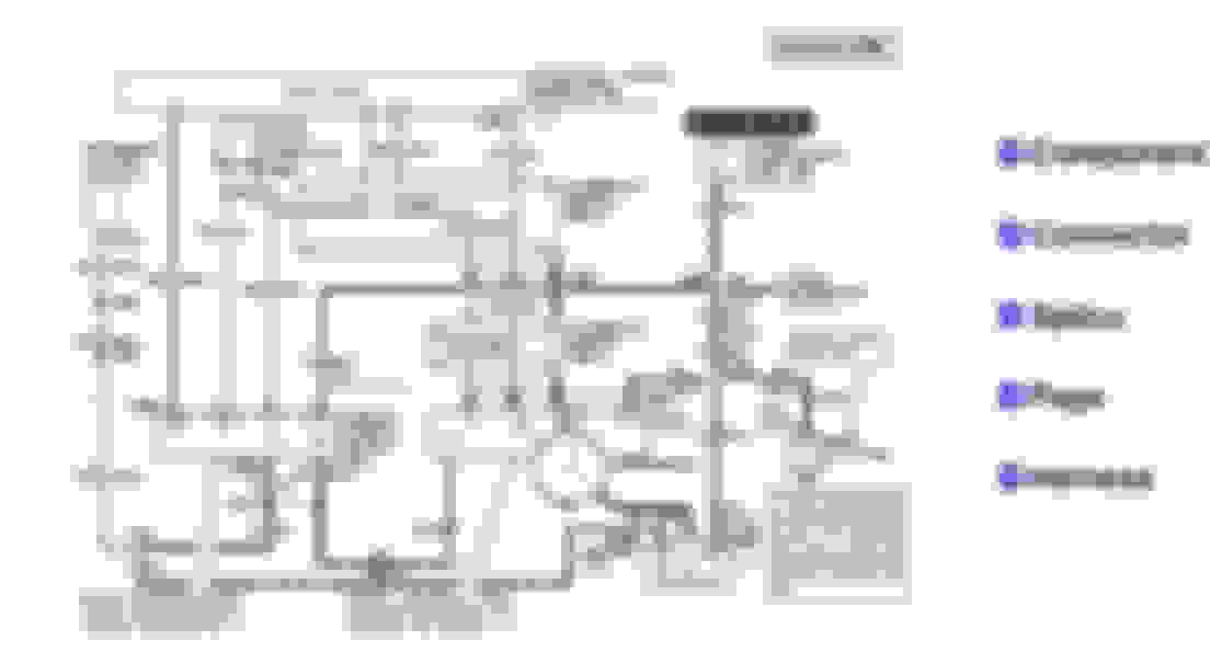
Does anyone have a schematic of the inside of the thin film pick up device?
A basic diagram from Subford:
[img][/img]
Be aware this is for a Push Start Ignition on 1993 and earlier Ford trucks. There is no Start signal into the ICM as depicted in the diagram. The 1994 and later trucks use a CCD style ignition so that pin is now an output (IDM) to the computer (PCM). The rest of the circuitry is the same.
Originally Posted by OceansideAirbrush
I'm starting to wonder if my ignition module is shorting when it gets warm and causing a spike that takes out the computer's driver for the injectors and kills the pick up in the distributor at the same time. I know for sure that computer drivers are taking longer 2 reset, I was able to see Square wave return from the distributor and it still would not start for another hour. I could see the square wave getting to the computer. So the computer took over an hour longer to decide to fire injectors again. So I really think I'm on to something with the driver circuit protection inside the computer. But I'm wondering if the pickup in the distributor may also have a circuit protected chip and when there is a spike both the computer and the distributor take a nap. found a used distributor at the Wreckers I'm going to pick it up today if my truck makes it there. I'll put together a video of the whole thing later.
You already proved the PIP signal is dropping out. Fix what you know is wrong before going down another bunny hole.
You have seen the PIP signal leave the distributor then go to the computer and the ICM in the diagrams. In the absence of a SPOUT signal from the computer the ICM will trigger on the PIP signal. Simple as that. I used the term RAW PIP signal from the Ford manual. That's how the engine still runs when the SPOUT plug is removed. It takes the computer out of the timing control path.
All I can tell you is what I read from the Ford manual. In the Ignition Troubleshooting it states if the PIP signal is great than 8 Volts, it's bad. The theory of a 50% duty cycle square wave would cause a lower reading with a DVM is sound and I agree with it. I would expect a lower voltage reading in this scenario. Since the PIP output is obviously getting compromised, as stated by you when using an oscilloscope, I would agree with the manual that a higher reading on the DVM is a result of a diminished square wave duty cycle from a bad PIP sensor.
No. it's a classic failure mode. They tend to fail like you are experiencing. There is no magic reset, it's a simple sensor prone to this type of failure.
A basic diagram from Subford:
[img][/img]
Be aware this is for a Push Start Ignition on 1993 and earlier Ford trucks. There is no Start signal into the ICM as depicted in the diagram. The 1994 and later trucks use a CCD style ignition so that pin is now an output (IDM) to the computer (PCM). The rest of the circuitry is the same.
You already proved the PIP signal is dropping out. Fix what you know is wrong before going down another bunny hole.
thanks for the reply and the valuable information. Especially the schematic that's great. Even if it's not exactly right for my truck it helps me see what's going on there. Sure doesn't look like any circuit protection there, but I am firmly convinced that circuit protection on the driver circuit in the PCM was affecting my injectors. I swapped out the distributor today. It died on me just as I got to the wrecking yard so I didn't have a choice. I popped it in right there with no timing light and it fired right up. However when it died on me last night at my shop, there was no more Square wave coming from the distributor yet I still have spark. That's the part I don't understand. There didn't even seem to be a raw Square wave it was more like barely registered a very long stretched-out sine wave that was barely even detectable. I don't see how this wave could trigger the module to spark. There was really nothing there at all except some voltage. Furthermore after I waited the two or three hours I was getting a square wave from the distributor again but still no injector pulse. I had already repaired the wire to the computer and I was sure it was getting continuity and receiving the same square wave pip signal yet it decided it did not want to fire injectors yet. I waited another hour and turn the key and it instantly started. That showed me that the computer did not want to fire injectors even when it was receiving the square wave after it died. Almost as if that Spike I saw put it over the top and it went into circuit protection mode. It's built into the chip. It turns the timer circuit to zero to protect the circuit. Also with the scope while it was running I could see that one of my injector Banks was not receiving a clean signal. The pin was not getting a good connection to the computer, there was corrosion deep in the pin socket and the pin socket was too loose. After fixing the wire 2 pin number 56 in the harness and fixing the wire to the injectors I still did not receive injector pulse of any kind. But after waiting the computer decided it was ready to fire injectors again. When it died at the records today there was no waiting time however it wasn't nearly as hot as it usually is because it's pretty close to my house. So after dropping the new distributor in it starts every time now. And I'm getting good signal to the computer and I'm getting a good injector pulse back. however the truck still runs like garbage mid throttle and pops and farts like it has ignition problems or a very lean mixture. When I unplug the throttle position sensor it idles much higher and still runs bad but it definitely seems to run a lot better and the misfires seem to go away. so I think my throttle position sensor is on its way out even though it seems to track perfectly and has the right amount of resistance close and open. I didn't buy the sensor yet because I want to check the wires and make sure they're not causing an issue first. There's also a chance that this symptom is still an ignition problem and could be my ignition module. I did switch it with another one when it was dead but it wouldn't start but that was because of the distributor. So maybe later after work I'll swap the ignition module and take it for a drive to see if that improves the mid throttle hesitation and misfiring. I did get codes back saying my throttle position sensor was leaving high voltage code stored in the computer, but it said the same thing about almost every sensor on my truck and I know they are not all failing. The throttle position sensor is in question at this moment it does run better without it. But I found so many wire issues and connections that were created on this truck from it being parked for a year-and-a-half on grass that there is something wrong with the wires or some corrosion in the harness. I have checked the connectors and it's fine. Just don't want to spend $70 on a sensor if I don't need it. But at least my truck starts every time I turn the key now so I'm getting somewhere with it.
If you're getting codes saying all your sensors are "High", that tends to indicate you have a sensor ground issue, a general EFI system ground issue or a failing PCM.
Make sure the ignition module is Black and not gray on the one that you replace it with.
Also make sure you have a good ground for the PCM computer on the passenger fender Body ground.
One of the small wires is the PCM Computer ground at the Body ground:
Rezvani's Latest Post-Apocalytic Monster Is a Ford F-150 Raptor Underneath
Slideshow: Called the Fortress, the 850-horsepower pickup combines Raptor underpinnings with military-inspired features, survival equipment, and a starting price of $285,000.


 [/img]
 [/img]


