When you click on links to various merchants on this site and make a purchase, this can result in this site earning a commission. Affiliate programs and affiliations include, but are not limited to, the eBay Partner Network.
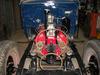
hi ! bring this back up again ,bought a hydrovac unit from orielly. installed it today but i,m unsure how to install the pipes. so here goes !! i suppose the mastercylinder goes to the hydrovac port thats the close to the diaphram. the other port supplies the pressure to the wheels. on the original hydrovac that port was bolted with a block that had 3 outlets. 2 for the front wheels and one for the rear brakes. now on this unit theres a 1/4 inverted flare outlet port. do i need a sort of 4 way block to distribute the pressure. heres a few pictures. first picture is the original hydrovac.
this ones got puzzeled. it comes from a old frame i got for parts. it had a hydrovac unit but i don,t remember if it was plumbed correctly as the frame was used as a trailer. i forgot to take a picture of the hydrovac unit but it was probably from the 50ies . but the mastercylinder had a block with multiple outlets i Wonder how it was set up.
is it possible that on that block, the outlets are not all hooked together. how could the hydovac pressure come back to the mastercylinder. i would like to have the least jonction as possible to eliminate possible leaks.
just and ideal what if i used my original 3 way block.like the first picture. i would have my brake switch and could plumb the front brakes on 2 outlets. the third one would go to the hydrovac , and it would only assist the rear brakes ! just thinking outloud!!!
thanks for any help brian.
That picture with the angle grinder in it, I have no idea what those two ports are for, they aren't on either of mine. What you want is a single line that goes from the master cylinder to the port in the booster closest to the diaphragm. The banjo bolt on the master cylinder should also be tapped 1/8" NPT for the stoplight switch. The banjo bolt on the end of the booster should have the three-way fitting that go to the wheel cylinders. I see where you have a newer style booster so my comments may not be applicable.
this ones got puzzeled. it comes from a old frame i got for parts. it had a hydrovac unit but i don,t remember if it was plumbed correctly as the frame was used as a trailer. i forgot to take a picture of the hydrovac unit but it was probably from the 50ies . but the mastercylinder had a block with multiple outlets i Wonder how it was set up.
I had a cast iron fitting similar to that originally. Correct, they are NOT all interconnected. The port with the coiled tube is connected to the master cylinder outlet, and goes to the Hydrovac booster inlet.
The opposite port is the high pressure return from the Hydrovac and is interconnected to the three other ports for the wheel cylinders.
I had a cast iron fitting similar to that originally. Correct, they are NOT all interconnected. The port with the coiled tube is connected to the master cylinder outlet, and goes to the Hydrovac booster inlet.
The opposite port is the high pressure return from the Hydrovac and is interconnected to the three other ports for the wheel cylinders.
thanks mixer man ! that would be my solution ! i will check that out . the hyrovac you posted looks like the one that was on my part frame.
thanks mixer man ! that would be my solution ! i will check that out . the hyrovac you posted looks like the one that was on my part frame.
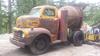
I don't know what size truck you have, but the pics I posted are the larger OEM Hydrovacs for the F-6. It can be noted that there were trailers back in the day that had hydraulic brakes with boosters that were vacuum operated. Those truck/trailer combinations had a single gladhand for vacuum and a hydraulic quick connect for the brake line.
hi ! bring this back up again ,bought a hydrovac unit from orielly. installed it today but i,m unsure how to install the pipes. so here goes !! i suppose the mastercylinder goes to the hydrovac port thats the close to the diaphram. the other port supplies the pressure to the wheels. on the original hydrovac that port was bolted with a block that had 3 outlets. 2 for the front wheels and one for the rear brakes. now on this unit theres a 1/4 inverted flare outlet port. do i need a sort of 4 way block to distribute the pressure. heres a few pictures. first picture is the original hydrovac.
this was my original 1942 hydrovac (it what was on truck when i got it ) . the master cylinder went to the diaphram side port ,and the 3 outlets were for 2 front wheels and one for the rear brakes. the vaccum cannister was like 2 1/2 the size of the one i got now. the vaccum part was fuctionnal, but the brake fluid had rusted up . thats the part they wanted like 700 dollars to repair.
my trucks a 2 ton . i Wonder how the connection was made between trailer and truck. i remember plumbing a trailer for a Buddy. i was a good while ago he had a small Suzuki samurai he used for firewood. i had used a brake hose for flex and 2 lines to trailer wheels he drove around with the trailer for years,because he could not unhook it !
my trucks a 2 ton . i Wonder how the connection was made between trailer and truck. i remember plumbing a trailer for a Buddy. i was a good while ago he had a small Suzuki samurai he used for firewood. i had used a brake hose for flex and 2 lines to trailer wheels he drove around with the trailer for years,because he could not unhook it !
just a regular hydraulic quick coupler , i bet they probably had spoogee brakes after a few trailer change.
Not that I can recall. Of course I wasn't driving then either. I just remember being around them and seeing them getting hooked up in the late '40's early '50's. By the late '50's all semi trucks had air brakes as far as I know.
This Hennessey Takes the Expedition Tremor's Off-Roading Capability to the Next Level
Slideshow: The VelociRaptor Expedition gains a lift, upgraded suspension, Brembo brakes, and trail-ready equipment while retaining the stock 440-horsepower EcoBoost V6.
Rezvani's Latest Post-Apocalyptic Monster Is a Ford F-150 Raptor Underneath
Slideshow: Called the Fortress, the 850-horsepower pickup combines Raptor underpinnings with military-inspired features, survival equipment, and a starting price of $285,000.