When you click on links to various merchants on this site and make a purchase, this can result in this site earning a commission. Affiliate programs and affiliations include, but are not limited to, the eBay Partner Network.
Hey guys,
I am getting real close to starting my 7.3 Idi in my centurion resto project. I swapped a rust free crew cab onto my 4x4 dually frame. Some of the wiring is a little screwed up and melted so i was hoping you guys could help me. What is c109 in this picture? Mine was melted and fixed but three of the wires were melted out of the plastic plug. Therefore, do you know where I can find a wiring diagram for that plug? The glow plugs do not work,( were converted to manual and I know they worked before the cab swap) and the starter doesn't engage with the key but the solenoid on the fender clicks and I can jump the solenoid to spin the motor. Do you guys know if this plug would have anything to do with those issues? It looks like that plug is part of the glow plug/engine harness. If not, then I'll just start tracing wiring and digging into things but regardless, those wires need fixed but I don't know what is supposed to go to what.
Also, where does the fuel shut off solenoid gets it's power from? The wire from this truck looks like it led to the starter solenoid on the fender.
I checked my 90 service manual there is no c109. If you have the manual that picture was taken from it should have it. But if it is the one I am thinking about it is the connector for the glow plug power. It is common for the two big wires to melt the connector. They are the one that send power to the glow plugs.
From the glow plug thread
waldrop4,
Welcome to FTE and the IDI diesel forum.
Voltage drop will have the voltage on the glow plug side of the relay lower when the glow plugs are heating.
200 amps through rather small AWG wire.
That said, there are two places you need to look.
First look at the chassis to engine connector, circled in red in this picture.
Click the image to open in full size.
That picture is on a 6.9 engine, so your is a little different.
In the picture the large AWG wires, orange color will be either yellow or tan on yours.
There will be two, both on the same end of the connector, You connector will be either black or white if I remember right.
Anyway, look for signs the connector has been hot, deformed or burnt looking plastic.
If you see that, the connector terminals are not making a good connection.
The only fix is to splice the wires aroung the connector, very common problem.
Caution, the wires are always hot, direct connection to the battery positive post.
In your diagram Connector 109 is obviously for the glow plugs/controller harness and is connected from the Positive post on the 'starter relay' at the fender well and controlled from the ignition switch - or whatever bypass wiring someone put in it.
I would assume (you can call it a guess) that someone had an electrical problem in the gp circuit, burned out the fuse link, spliced the wires back together without a fuse link and without identifying the original problem and fixing it this caused the wires and plug to burn up.
I can help with schematic images (if I have enough time to get them posted at this moment) from the 1987 shop manuals (solid state gp controller)
Wiring should be the same possibly a different color of wire somewhere but I'm inclined to think they would be the same and you are working on a 1989 truck, right? Don't know what your diagram is from.
No Connector 109 in the 87 manuals.
First, the FSV:
FSV is powered from the ignition switch: R/LG wire (Red/LightGreen) There is a Fuse Link labeled 'V' in that circuit 20 Gauge BLUE. S216 and S156 are "splices" and I figured out that sometimes "splices" in a schematic are inside a connector (plug) where 2 wires are joined into one terminal of the connector:
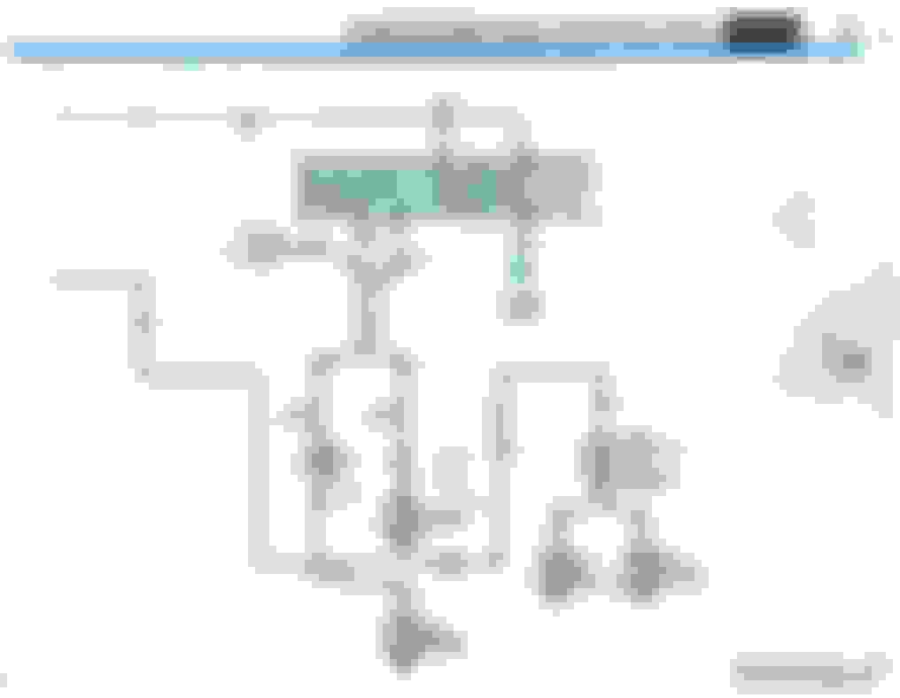
No time to discuss these at the moment but here are a few of the relevant schematics that I have - I hope you can follow them and trace from one page to the next appropriate page. I'll number these 22, 23, 24, etc.:
IMAGE 22: CHARGE-POWER DISTRIBUTION DIESEL
I'll skip image 23 for now as "not needed" and go to image 24. You will be following the lower Yellow wire that goes to the ignition switch. That is the power wire that feeds the ignition switch and as you can see - also the FSV as in my first post and the other things from the ignition switch. NOTE: The OrangE/Black STripe wires you need to follow will be in a glow plug/controller schematic:
IMAGE 24: CHARGE-POWER DISTRIBUTION DIESEL
I hope I described that close to correct so far. I know you'll need more but I am in a very big rush right now!
Regarding Other images I wanted to post here- glow plug controller circuit etc. I accidentally deleted a folder awhile back where I had saved important schematics images for quick access and I see that I have not replaced those yet so I will have to wait until later to look them up in the shop manuals (3600 pages - it can be very time consuming to find things, thus the reason for creating page image copies in quick access folders).
I was trying to delete duplicate files and folders and I ended up accidentally deleting the important folders I wanted to keep. That was a lot of work I deleted - happened from typical lack of sleep and being too tired to pay proper attention.
I might have some of those on a back-up drive but I can't look until later this evening. Otherwise I'll look them up again.
CREDIT FOR THESE IMAGES IS SHOWN IN THE LOWER RIGHT CORNER OF THE FIRST ONE I POSTED. Scans on CD from Original 1987 Ford Motor Company Light Truck, Van and Bronco Shop Manuals, Licensed to David Graham 2012 for distribution and sale.
Wow thanks! I will definitely put these to good use. I've got a busy weekend ahead of me but I'm hoping I can work on the truck some this weekend. It looks like from my glue plug harness, that the two yellow wires go to the two black w/ orange stripe. But I'll have to figure out if it matters which yellow wire goes to which black w/ orange or if they could be hooked up to either one.
Rezvani's Latest Post-Apocalytic Monster Is a Ford F-150 Raptor Underneath
Slideshow: Called the Fortress, the 850-horsepower pickup combines Raptor underpinnings with military-inspired features, survival equipment, and a starting price of $285,000.