


fuel injection ???

Thread Starter
|
Freshman User
Joined: Dec 2002
Posts: 40
Likes: 0
From: ohio
fuel injection ???
hey everybody, just pulled an 86 5.0 from a crown vic. anybody know what part of the wiring harness is most important when i drop this engine in my 77 bronco? i marked all the wires the best i could but it seems like they are never ending. also, there are a ton of vacuum lines all over the place, any ideas which ones are mandatory. is the air pump even needed? i just want to eliminate anything i can now so i end up with a clean instalation.
Postmaster
Joined: Dec 2002
Posts: 3,594
Likes: 2
From: Southern Oregon USA
fuel injection ???
You need the entire harness that goes through the firewall to the ECM from the engine compartment. The entire engine harness itself. The O2 harness, which may go under the front of the engine and back toward the exhaust. You also want to grab all of the sensors attached to these harnesses.
These sensors and actuators include:
MAP sensor
EGR pressure regulator
TAB solenoid
TAD solenoid
Main ECM relay
You will also want to locate and cut the fuel pump relay and plug. Some are located in the trunk. You will have to splice it into the Main harness to suit your needs.
As far as the vacuum that you need, here are the basics:
You need vacuum to the MAP sensor, EGR regulator, and from the regulator to the EGR valve.
You can get rid of the air pump and related stuff, such as the TAB and TAD solenoids. I plug them into the harness, but don't have any vacuum to them to keep from setting any codes. The same with the charcoal canister solenoid. You also don't need a cat converter if you are smog exempt.
In most applications, the main engine harness is connected to the body harness with quick disconnects. I cut the wires on the body harness side and kept the connectors. I have recently did away with all of those connectors to clean up under the hood. You will need to get a good wiring diagram for the year of your car to figure out which of those wires are needed and what they connect to.
HTH,
Jason
Thread Starter
|
Freshman User
Joined: Dec 2002
Posts: 40
Likes: 0
From: ohio
fuel injection ???
hey jason, thanks for all the help. i'm the guy that bought your c-bushing mounts off your dana 30 so i could use them on a dana 60. they worked out great! as far as the fuel injection goes, can you suggest a book or web site that will help me identify all the sensors and actuators? i want to make sure i don't forget anything before i scrap the car.
Postmaster
Joined: Dec 2002
Posts: 3,594
Likes: 2
From: Southern Oregon USA
fuel injection ???
Glad to hear they worked out for you.
Ford EFI book
This is the must have book, IMO. I know it doesn't cover your '86 model specifically, but the information still applies. It is a great book that tells you how everything functions together, diagnostic procedures, wiring diagrams, and shows pictures and schematics of almost everything.
Jason
Thread Starter
|
Freshman User
Joined: Dec 2002
Posts: 40
Likes: 0
From: ohio
fuel injection ???
hey jason, i located most of the sensors i need. can you shed some light on the tab and tad solenoids? i'm not sure what these are and where to locate them. also, the map sensor(manifold absolute pressure). i think i know where it is but want to be sure. i'm also under the impression that this engine does not have the mass air flow sensor because of the map sensor. mass air flow came in later years, correct??
Postmaster
Joined: Dec 2002
Posts: 3,594
Likes: 2
From: Southern Oregon USA
fuel injection ???
The TAB controls the air from the smog pump to the TAD. When no downstream (secondary) air is needed, it bypasses the system. When secondary air is needed, the TAB allows air to go to the TAD. The TAD diverts the air either upstream to the exhaust manifold(s) or sends it downstream to the catalytic converter.
Most of the time, the TAB and TAD solenoids are found on the passenger side fender. It depends on the body for sensor locations. On my donor, the MAP was on the firewall behind the engine. Others have them located on the pass fender, pass firewall area.
On the HO engine, MAF was first available in '87 on Calif emissions cars. Federal emissions cars did not get MAF until '89.
I'm not sure about the cutoff for the non HO passenger car availability. But your '86 will definetely be MAP (or speed density)
Here are some pictures: The first shows the MAP sensor (with the EGR pressure regulator on the left). The second is a closer view of the MAP, but it is a little blurry. The third picture is the TAB and TAD solenoids. They are identical.


Hope that helps you out.
Jason
Most of the time, the TAB and TAD solenoids are found on the passenger side fender. It depends on the body for sensor locations. On my donor, the MAP was on the firewall behind the engine. Others have them located on the pass fender, pass firewall area.
On the HO engine, MAF was first available in '87 on Calif emissions cars. Federal emissions cars did not get MAF until '89.
I'm not sure about the cutoff for the non HO passenger car availability. But your '86 will definetely be MAP (or speed density)
Here are some pictures: The first shows the MAP sensor (with the EGR pressure regulator on the left). The second is a closer view of the MAP, but it is a little blurry. The third picture is the TAB and TAD solenoids. They are identical.
Hope that helps you out.
Jason
Last edited by RCrawler; Jul 10, 2003 at 01:04 AM.
Trending Topics
Thread Starter
|
Freshman User
Joined: Dec 2002
Posts: 40
Likes: 0
From: ohio
fuel injection ???
hey guys, thanks for the help again. jason, if you put all the info you know about broncos in book form you wouldn't have to work ever again. thanks for being so outgoing with all the info and i'm sure i'll be asking more questions soon.
FTE Stories
Ford Trucks for Ford Truck Enthusiasts

3 Best / 3 Worst Parts of Modern Ford Ownership
Brett Foote
10 Amazing Upgrades That Solve Common Ford Truck Owner Headaches
Pouria Savadkouei
Every 2026 Ford Engine Explained
Brett Foote
10 Ugly Ford Trucks That We Still Kinda Love
Joe Kucinski
10 Things Every Truck Owner NEEDS (2026 Edition)
Michael S. Palmer
Rezvani's Latest Post-Apocalyptic Monster Is a Ford F-150 Raptor Underneath
Verdad Gallardo
Top 10 Most Expensive Ford Trucks Ever Sold on Bring a Trailer
Joe Kucinski
2027 Ford Super Duty Buyer's Guide (Every Model, Engine, & Package)
Brett Foote
Top 10 Ford Truck Tragedies
Joe Kucinski
Thread Starter
|
Freshman User
Joined: Dec 2002
Posts: 40
Likes: 0
From: ohio
fuel injection ???
okay, the engine isn't even in the truck yet but here's another question. now that electronics have been labled and identified, i'm under the impression that whatever is still atached to the fuel injection wiring harness can be dicarded. basically just cut off anything that no longer serves a purpose. also, when hooking up 12 volt power to the injected harness from the stock bronco harness. where is the best location on the stock harness to feed the injected harness? will one 12 volt wire be able to feed the new harness or do some things need fed seperatley. any info will help, i'm hoping to drop in 5.0 soon. thanks alex
Post Fiend
Joined: Nov 2002
Posts: 9,987
Likes: 7
From: Memphis, TN
fuel injection ???
Jason
What year was your donor? That sloped side on your MAP suggests it's the old voltage-varying type instead of the more common later frequency-varying type.
Most trucks (all '87-96 F-series & Bronco) have the TAB, TAD, & EVR on the engine, with the MAP on the R top of the firewall.
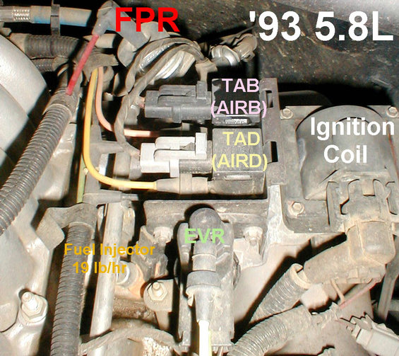
On this truck, I think they're in about the same place, which is hidden by the master cylinder. It's been a few years since I built it, so I don't remember exactly, but I know it's in the stock location for the Crown Vic that the intake & plenum came from.


What year was your donor? That sloped side on your MAP suggests it's the old voltage-varying type instead of the more common later frequency-varying type.
Most trucks (all '87-96 F-series & Bronco) have the TAB, TAD, & EVR on the engine, with the MAP on the R top of the firewall.
On this truck, I think they're in about the same place, which is hidden by the master cylinder. It's been a few years since I built it, so I don't remember exactly, but I know it's in the stock location for the Crown Vic that the intake & plenum came from.
Last edited by steve83; Jul 11, 2003 at 11:33 AM.
Postmaster
Joined: Dec 2002
Posts: 3,594
Likes: 2
From: Southern Oregon USA
fuel injection ???
Originally posted by steve83
[B]Jason
What year was your donor? That sloped side on your MAP suggests it's the old voltage-varying type instead of the more common later frequency-varying type.
[B]Jason
What year was your donor? That sloped side on your MAP suggests it's the old voltage-varying type instead of the more common later frequency-varying type.
That sure is a clean swap you did. Nice work.
Jason
Postmaster
Joined: Dec 2002
Posts: 3,594
Likes: 2
From: Southern Oregon USA
fuel injection ???
Originally posted by amtocco
okay, the engine isn't even in the truck yet but here's another question. now that electronics have been labled and identified, i'm under the impression that whatever is still atached to the fuel injection wiring harness can be dicarded. basically just cut off anything that no longer serves a purpose. also, when hooking up 12 volt power to the injected harness from the stock bronco harness. where is the best location on the stock harness to feed the injected harness? will one 12 volt wire be able to feed the new harness or do some things need fed seperatley. any info will help, i'm hoping to drop in 5.0 soon. thanks alex
okay, the engine isn't even in the truck yet but here's another question. now that electronics have been labled and identified, i'm under the impression that whatever is still atached to the fuel injection wiring harness can be dicarded. basically just cut off anything that no longer serves a purpose. also, when hooking up 12 volt power to the injected harness from the stock bronco harness. where is the best location on the stock harness to feed the injected harness? will one 12 volt wire be able to feed the new harness or do some things need fed seperatley. any info will help, i'm hoping to drop in 5.0 soon. thanks alex
1. One wire will go directly to Bat + to feed the fuel pump relay
2.One wire will go to Bat + to feed the EEC relay (main ECM relay)
and supply ECM for memory
3. You will have 3-4 ground wires. I have everything grounded, body, frame, and engine. I have a large gauge wire from Bat - to a sealed junction box to connect ECM grounds. Very important to have proper ground connections.
4. One wire will get Crank only signal, feeds ignition module. This can come from the starter solenoid S terminal or ignition switch. Make sure you get a diode protected solenoid.
5.One wire will feed ignition coil and module with Crank and run signal. Same wire should also trigger the EEC relay. You can get this power right at the ignition switch or at one of the wires at the OE voltage regulator. Do not attempt to hook this to the coil feed under the hood. That wire has a resistor and won't supply enough power.
6. Not sure if your O2 is heated or not. If it is, you will need a a Crank and run signal. I have mine on a relay to ensure that it gets clean power.
7. There is also a O2 ground that comes out of the O2 harness to connect to ground somewhere on the engine.
8. There is another ground (bare wire) near the ECM. I have it grounded to one of the ECM attaching straps.
That should get you started in figuring it out. I'm sure I've missed something in there.
Jason


Thread Starter
|
Freshman User
Joined: Dec 2002
Posts: 40
Likes: 0
From: ohio
fuel injection ???
thanks again guys, i'll try to get some pics up soon so you can see the progress. couple of more questions and i should be done for a little while. the 86 crown vic oil pan looks identical to the stock 77. is it worth it to swap out? also, since i eliminated the smog pump,(there are not any emmission checks where i live), i was able to eliminate 40 miles of vacuum hose and tubing. with exception of the MAP,EGR reg.,and EGR valve i'm guessing that i can block off any vacuum ports that will no longer be used. does this sound like a good idea? where is the best source to supply vacuum to the needed sensors?
Postmaster
Joined: Dec 2002
Posts: 3,594
Likes: 2
From: Southern Oregon USA
fuel injection ???
Originally posted by sgreen
What is the recommended method to utilize the later model alternator with an integral regulator?
S
What is the recommended method to utilize the later model alternator with an integral regulator?
S
Wiring a 3G Mustang Alternator to an EB
What you'll need from the Bronco:
Intact factory wiring harness
*Wiring diagram (not absolutely necessary) the only reason you would need this is if your wiring is a complete mess, and I would recommend getting things like that in order before doing this upgrade.
What you'll need from the Mustang:
*Alternator harness. This can be found at your local junkyard, or by going to NAPA and purchasing just the plug for $18. The plug is all you really need, and is clean and new.
* 1-16 ga. fusible link (NAPA)
* 1-14 ga. fusible link (NAPA)
* 1-18 ga. fusible link (NAPA)
* Electrical butt connectors (solder type, heat shrink type recommended)
In the Bronco harness, trace back 'upstream' from the stock alternator/regulator wiring to somewhere along the passenger's side fenderwell. Open the harness and locate the following wires:
1. Black/yellow stripe wire, -10-12 ga.
2. Black/red stripe (73-'77) or black wire ('66-'72), -10-12 ga.
3. Green/ red stripe wire 16 ga.
On the Mustang plug, locate the following wires:
1 white/ black wire 14-16 ga.
1 green/ red wire 14-16 ga.
1 yellow/ white stripe wire 12-14 ga.
Make sure you have enough of the correct gauge wiring, and connect the following:
1.IF YOU USE JUST THE MUSTANG PLUG-- Black/yellow stripe wire in the Bronco harness needs to mate with a 12 ga wire that you run from the post on the back of the Alternator. These two wires will then go to the + post on the starter solenoid using a 14 ga. fusible link. I would assume that you could run each of these individually to the + post with their own fusible links, but I ran it the above way to keep from having more connections on my solenoid.
1a. IF YOU USE A MUSTANG ALTERNATOR HARNESS-- Black/yellow stripe wire to one of the black/orange stripe wires in the Mustang alternator harness. Connect the other black/orange stripe wire in the Mustang harness to the positive (hot) post of the starter solenoid using a 14 ga. fusible link.
2. *******Black/red ('73-'77) or black ('66-'72) wire in Bronco harness to a 16 ga. fusible link. Attach fusible link to positive (hot) post of starter solenoid. ********This step was omitted in my wiring, as it did not apply. I had a black/ red with that came from the �sta� post on my alt and went to ground. Whether this was correct or not, I do not know, but that wire was not needed, as you would not want to run + to � on any connection.
3. Green/red stripe wire in the Bronco harness will be connected to the green/red stripe wire in the Mustang alternator harness.
4. Yellow/white stripe wire in Mustang harness to an 18 ga. fusible link. Attach fusible link to the positive + post of starter solenoid.
5. Remove external regulator and lots of old, now useless, cluttered wiring from the truck! I removed a yellow wire, an orange wire, and the regulator itself.
Hook up the battery and look for smoke! Get out your voltmeter and check for 14-15 volts at the battery positive post. My battery was at 13 volts and shot to 14.6. The norm is 14.4 to 14.7 from what I have read.
Notes
The # 1a connection above could be done several different ways since both black/orange wires in the Mustang wiring harness carry the alternator output. Another way would be to not separate the two wires and run one black/orange wire to the black/yellow wire in the Bronco harness. However, this means that the battery is receiving its power after running all the way back through the ammeter wiring, fuse block, etc. Tying one of the output lines to the starter solenoids hot post gives a short feed line to the battery.
*Don't skimp on the electrical connectors. I used NAPA Sure-Seal connectors that provide a solid, soldered mechanical connection that's well protected with adhesive-lined shrink sleeves. The connections from the new 3G Alternator to the solenoid need to be stable waterproof connections. Black tape and twisting the wire is not going to last, and could have adverse effects on your wiring.
This setup results in a much cleaner wiring harness under the hood! I was amazed how much old wiring I was able to remove with this transplant.
Some people recommend using the Mustang fusible links to hook up the various wires. I found it much easier to run down to NAPA and get brand new links off their electrical rack.
Originally Compiled by Clint Eddy & Todd Zuercher