
Power Distribution Box Schematic?

Thread Starter
|
FTE Legend


Joined: Jul 2010
Posts: 32,875
Likes: 48
From: Northeast, OK
Power Distribution Box Schematic?
Hi, guys. I'm restomoding my father's '81 F150. And one change I'm making is to install a power distribution/fuse/relay box under the hood - along with a 3G upgrade. My buddy Bruno2 grabbed a couple of the boxes at a salvage recently, one from a Taurus and one from a Ford pickup. But, I'm not sure what it is off of. The folks in the 87 - 96 forum say it looks later than from their trucks. And the lid (F65B-14A003-C) was apparently used an many different vehicles as I've found hits from the late 90's to at least 2002.
I would really like to find a schematic of the box rather than have to build my own, so I'm hoping someone has one. Here's a shot of the box. And, thanks in advance.

I would really like to find a schematic of the box rather than have to build my own, so I'm hoping someone has one. Here's a shot of the box. And, thanks in advance.


Moderator


Joined: Jan 2001
Posts: 56,997
Likes: 2,746
From: Virginia

Ohmmeter may be the best way. There is a thread in here somewhere where a guy shows how to take these things apart and get rid of what you don't need. I will look a little bit and see if I can find it.
Moderator
Joined: Jan 2001
Posts: 56,997
Likes: 2,746
From: Virginia
Thread Starter
|
FTE Legend
Joined: Jul 2010
Posts: 32,875
Likes: 48
From: Northeast, OK
Thanks, Dave. I have the DVM set on Continuity and have already figured out that the battery lug powers all of the fuses. And with the exception of one fuse, which goes to one of the Bosch relays, all of the fuses have their outputs open. And the other two Bosch relays have open leads as well. So all I have to do now is to check out the three micro relays and I'll have a good picture of the box. And, since almost everything isn't interconnected it should be easy to use.
Also, thanks for the link to that thread. I'll see if mine comes apart that way, but right now I don't think I'll need to take it apart any further.
Also, thanks for the link to that thread. I'll see if mine comes apart that way, but right now I don't think I'll need to take it apart any further.
Thread Starter
|
FTE Legend
Joined: Jul 2010
Posts: 32,875
Likes: 48
From: Northeast, OK
I'm creating a diagram for the box, and here's what I've found so far:
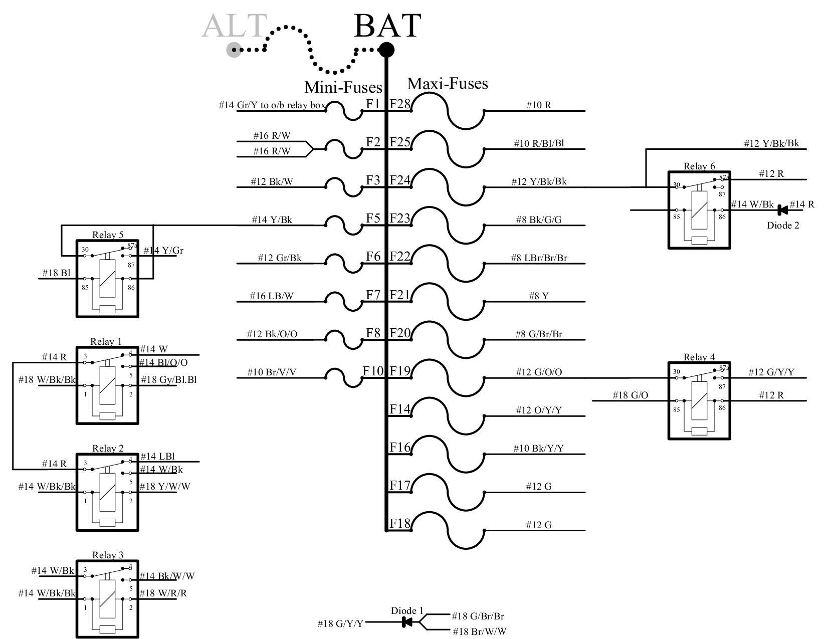
- Fuses: All fuses are on a buss off of the battery stud
- Alternator Stud: This box doesn't have an alternator stud, but studs from other boxes will fit if a red plastic piece is removed. And that allows a Megafuse to be installed across them.
- There is a wide range of wire sizes so you can pick one that matches up with the size of wire that you are splicing in
Last edited by Gary Lewis; May 8, 2014 at 01:08 PM. Reason: Fix glaring errors.

Thread
Thread Starter
Forum
Replies
Last Post
FordTruckfan89
Pre-Power Stroke Diesel (7.3L IDI & 6.9L)
3
Feb 16, 2015 12:35 PM
MONAVIERONJON
Pre-Power Stroke Diesel (7.3L IDI & 6.9L)
1
Jan 8, 2010 10:44 PM


