




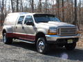


Plastic Fender (Rub) Pull-Back Mod

Thread Starter
|
Logistics Pro


Joined: May 2011
Posts: 4,832
Likes: 668
From: Maine
Only 1-1.5mpg. I adjusted the speedo/odo using Auto Enginuity, too. (ABS module.) I used a $100 Zone Offroad adjustable tracbar.
Thread Starter
|
Logistics Pro
Joined: May 2011
Posts: 4,832
Likes: 668
From: Maine
Thread Starter
|
Logistics Pro
Joined: May 2011
Posts: 4,832
Likes: 668
From: Maine
I'd suggest you think twice then. For the money you're about to spend, you could just about get a 4" lift.
How much are you going to spend on the shackles, track bar and shocks for just a leveling kit? Ford Super Duty 4.5 inch Hanger Lift Kit - Sky's Off-road Design
Add some rear blocks and u-bolts and you've got the lift you want and you only have to do it once.
Edit: Torque specs
Torque Specifications Description Nm lb-ft
Front spring-to-axle U-bolts 133 99
Front spring-to-spring hanger nut 275 203
Front spring-to-shackle nut 250 185
Spring hanger-to-frame bolts 103 76
Spring shackle-to-frame nut 250 185
Stabilizer bar-to-front spring spacer bolts (LH side only) 55 41
Stabilizer bar-to-axle assembly bracket bolts (RH side only) 55 41
Stabilizer bar-to-link nut 109 80
Stabilizer bar link-to-bracket nut 109 80
Front shock-to-upper shock bracket nut 103 76
Front shock-to-front spring spacer nut 103 76
Jounce bumper-to-frame bolts 40 30
Shock absorber upper mounting bracket-to-frame bolts 103 76
Track bar-to-upper mounting bracket nut 550 406
Track bar-to-lower mounting bracket nut 550 406
Shackle bracket assembly-to-frame bolts 90 66
Stabilizer bar bracket-to-frame bolts 47 35
Front driveshaft-to-pinion flange bolts 102 76
Front hub and bearing-to-knuckle nuts 74 55
Tie-rod end-to-front knuckle nut 70 52
Lower ball joint nut 204 150
Upper ball joint nut 94 69
How much are you going to spend on the shackles, track bar and shocks for just a leveling kit? Ford Super Duty 4.5 inch Hanger Lift Kit - Sky's Off-road Design
Add some rear blocks and u-bolts and you've got the lift you want and you only have to do it once.
Edit: Torque specs
Torque Specifications Description Nm lb-ft
Front spring-to-axle U-bolts 133 99
Front spring-to-spring hanger nut 275 203
Front spring-to-shackle nut 250 185
Spring hanger-to-frame bolts 103 76
Spring shackle-to-frame nut 250 185
Stabilizer bar-to-front spring spacer bolts (LH side only) 55 41
Stabilizer bar-to-axle assembly bracket bolts (RH side only) 55 41
Stabilizer bar-to-link nut 109 80
Stabilizer bar link-to-bracket nut 109 80
Front shock-to-upper shock bracket nut 103 76
Front shock-to-front spring spacer nut 103 76
Jounce bumper-to-frame bolts 40 30
Shock absorber upper mounting bracket-to-frame bolts 103 76
Track bar-to-upper mounting bracket nut 550 406
Track bar-to-lower mounting bracket nut 550 406
Shackle bracket assembly-to-frame bolts 90 66
Stabilizer bar bracket-to-frame bolts 47 35
Front driveshaft-to-pinion flange bolts 102 76
Front hub and bearing-to-knuckle nuts 74 55
Tie-rod end-to-front knuckle nut 70 52
Lower ball joint nut 204 150
Upper ball joint nut 94 69
SECTION 204-01B: Front Suspension — 4x4 2001 F-Super Duty/Excursion/Motorhome Chassis Workshop Manual
REMOVAL AND INSTALLATION Procedure revision date: 02/27/2003
--------------------------------------------------------------------------------
Spring —Leaf
Removal
Remove the wheel and tire assembly. For additional information, refer to Section 204-04 .
Position jack stands under the axle housing.
NOTE: The following step is for the left-hand shock only.
Remove the shock.
Remove the nut and bolt.
Remove the shock from the front spring cap.
CAUTION: Never reuse U-bolts. The U-bolts are a torque-to-yield design and cannot be retightened. Failure to use a new U-bolt can result in loose or broken springs and suspension components.
Remove the U-bolts.
Remove the four nuts.
Remove the two U-bolts and the front spring spacer. Discard the U-bolts.
Disconnect the front driveshaft.
Remove the four bolts and the two straps.
Remove the driveshaft from the pinion flange.
Disconnect the spring shackle.
Remove the nut and bolt.
Position the spring shackle away from the spring.
Detach the pushpin and remove the bolt and condenser bracket.
Disconnect the spring hanger.
Remove the nut and bolt.
Using a hammer, tap the spring until the spring is free from the hanger bracket.
Remove the spring from the vehicle.
Installation
Position the spring in the vehicle.
Install the spring into the spring hanger.
Position the spring into the hanger.
Install the bolt and nut. Do not tighten the nut and bolt at this time.
Install the bracket and bolt and the pushpin.
Install the spring into the spring shackle.
Position the shackle.
Install the bolt and nut. Do not tighten the nut and bolt at this time.
NOTE: The U-bolts insert through the front spring cap on the left-hand side and through the axle assembly bracket on the right-hand side.
Install the upper front spring spacer and U-bolts.
Position the front spring spacer and the new U-bolts.
Install the four nuts. Do not tighten the nuts at this time.
NOTE: The following step is for the left-hand shock only. The right-hand shock is similar.
Install the shock, bolt and nut onto the spring cap.
NOTE: The suspension must be loaded with the weight of the vehicle before the U-bolts and the leaf spring mounting bolts can be tightened. Make sure that the locating pin is correctly aligned with the axle.
Lower the vehicle onto the jack stands until the front suspension is supporting the weight of the vehicle.
NOTE: The U-bolts must be tightened in a criss-cross sequence. This will tighten the U-bolts evenly.
Tighten the U-bolts following the sequence.
Tighten the leaf spring rear retaining bolt and nut.
Tighten the leaf spring front retaining bolt and nut.
Raise the vehicle and remove the jack stands.
Install the front driveshaft.
Position the driveshaft onto the pinion flange.
Install the two straps and the four bolts.
Install the wheel and tire assembly. For additional information, refer to Section 204-04 .
REMOVAL AND INSTALLATION Procedure revision date: 02/27/2003
--------------------------------------------------------------------------------
Spring —Leaf
Removal
Remove the wheel and tire assembly. For additional information, refer to Section 204-04 .
Position jack stands under the axle housing.
NOTE: The following step is for the left-hand shock only.
Remove the shock.
Remove the nut and bolt.
Remove the shock from the front spring cap.
CAUTION: Never reuse U-bolts. The U-bolts are a torque-to-yield design and cannot be retightened. Failure to use a new U-bolt can result in loose or broken springs and suspension components.
Remove the U-bolts.
Remove the four nuts.
Remove the two U-bolts and the front spring spacer. Discard the U-bolts.
Disconnect the front driveshaft.
Remove the four bolts and the two straps.
Remove the driveshaft from the pinion flange.
Disconnect the spring shackle.
Remove the nut and bolt.
Position the spring shackle away from the spring.
Detach the pushpin and remove the bolt and condenser bracket.
Disconnect the spring hanger.
Remove the nut and bolt.
Using a hammer, tap the spring until the spring is free from the hanger bracket.
Remove the spring from the vehicle.
Installation
Position the spring in the vehicle.
Install the spring into the spring hanger.
Position the spring into the hanger.
Install the bolt and nut. Do not tighten the nut and bolt at this time.
Install the bracket and bolt and the pushpin.
Install the spring into the spring shackle.
Position the shackle.
Install the bolt and nut. Do not tighten the nut and bolt at this time.
NOTE: The U-bolts insert through the front spring cap on the left-hand side and through the axle assembly bracket on the right-hand side.
Install the upper front spring spacer and U-bolts.
Position the front spring spacer and the new U-bolts.
Install the four nuts. Do not tighten the nuts at this time.
NOTE: The following step is for the left-hand shock only. The right-hand shock is similar.
Install the shock, bolt and nut onto the spring cap.
NOTE: The suspension must be loaded with the weight of the vehicle before the U-bolts and the leaf spring mounting bolts can be tightened. Make sure that the locating pin is correctly aligned with the axle.
Lower the vehicle onto the jack stands until the front suspension is supporting the weight of the vehicle.
NOTE: The U-bolts must be tightened in a criss-cross sequence. This will tighten the U-bolts evenly.
Tighten the U-bolts following the sequence.
Tighten the leaf spring rear retaining bolt and nut.
Tighten the leaf spring front retaining bolt and nut.
Raise the vehicle and remove the jack stands.
Install the front driveshaft.
Position the driveshaft onto the pinion flange.
Install the two straps and the four bolts.
Install the wheel and tire assembly. For additional information, refer to Section 204-04 .

FTE Stories
Ford Trucks for Ford Truck Enthusiasts

AEV FXL Super Duty - the Super Duty Raptor Ford Doesn't Make
Brett Foote
Lobo Vs Lobo: Proof the F-150 Lobo Should Be Even Lower!
Michael S. Palmer
Ford's 2001 Explorer Sportsman Concept Looks For a New Home
Verdad Gallardo
10 Best Ford Truck Engines We Miss the Most!
Joe Kucinski
2026 Shelby F-150 Off-Road: Better Than a Raptor R?
Brett Foote
2027 Super Duty Carhartt Package First Look: 12 Things You NEED to Know!
Michael S. Palmer
10 Most Surprising 2026 Ford Truck Features!
Joe Kucinski
Top 10 Ford Trucks Coming to Mecum Indy 2026
Brett Foote
5 Best / 5 Worst Ford Truck Wheels of All Time
Joe Kucinski
Cargo Master
Joined: Jan 2005
Posts: 2,902
Likes: 2
From: Pasadena, Maryland

I put my 315's on today and it is rub city. I cut the front bumper but am rubbing on the fender at the rear of the wheelwell. I used x code springs with a BDS add a leaf. My truck now sits level. I am thinking about Bushwacker fender flares but I am extremely hesitant about cutting the fender. My 16x10 rims have 4.5 inch backspacing.
Thread Starter
|
Logistics Pro
Joined: May 2011
Posts: 4,832
Likes: 668
From: Maine
I put my 315's on today and it is rub city. I cut the front bumper but am rubbing on the fender at the rear of the wheelwell. I used x code springs with a BDS add a leaf. My truck now sits level. I am thinking about Bushwacker fender flares but I am extremely hesitant about cutting the fender. My 16x10 rims have 4.5 inch backspacing.

Cargo Master
Joined: Jan 2005
Posts: 2,902
Likes: 2
From: Pasadena, Maryland
My offset is way off. These rims are for BIG tires, not 34's...

Thread
Thread Starter
Forum
Replies
Last Post