When you click on links to various merchants on this site and make a purchase, this can result in this site earning a commission. Affiliate programs and affiliations include, but are not limited to, the eBay Partner Network.
I've pulled the dash to install a new head unit and will also be installing some new switches & gauges. My truck does not have the 4x4 shift on the fly switch as it's a manual floor shifter, nor does it have the air bag on/off switch, but there are 2 plugs back there and I would like to know which wires provide what. By this I'm asking which wire would be constant power, which wire would be ground, which wire would be for the dash/running light illumination?
I also have some factory Ford push button switches I'll need help with. It looks like the 5 wires are placed in the same locations within the plug-in, though some of the wires are a different color. I'm assuming there is a power in, power out, a ground, a dash/running light coming from the headlight switch to illuminate the face of the button, etc. If you remove the plug you can see the spade connectors are numbered, which may be an easier way to look at which wire does what. There are spades numbered for 1, 2, 4 on the first row and 6 & 8 on the second row. Best I can figure in looking at the wire thickness & color is spade 6 is for constant power in and spade 2 is for switched power out. Both switches have a black wire in spade 4 so I'd think that would be ground. This leaves spades 1 & 8 and 8 has a blue with red trace wire in both, so I'm thinking that may be for the front face illumination coming from the dash/running lights. The wires in spade 1 are of a different color and I'm not sure what else that could be for and/or if my aforementioned assumption would be correct.
^^^...plug for 4x4 switch on the fly...
^^^...plug for air bag on/off...
^^^...push button switch for defrost...
^^^...push button switch for fog lights...
^^^...plug-ins for push button switches...
^^^...spades for push button switches...
Oh, almost forgot about the other plug under the dash just above the drivers foot well that I believe was for a brake controller. Might be good to know what those wires would be for too given my brake controller in there now is wired separately, but in thinking about it I guess it could also be for a high idle module.
The last photo in your set of pictures is NOT for the trailer brake controller. It is indeed for the Auxiliary Powertrain Control Module (APCM), which you described as the high idle module.
The trailer brake controller connector is rectangular, brown in color, with 6 cavities, although only 4 cavities are utilized, while a 5th cavity may or may not be used, depending on whether the trailer brake controller has dashpanel illumination.
I�m not much help but normally the light blue with red is for illumination on the Fords I�ve worked with.
These will be simple to check with a test light. Start by grounding the light and searching for the constant on, key on power, and confirm the blue is controlled by lights. Then connect to the constant on to search for the ground. At least that�s how I�d do it. A multimeter would probably be the �most approved� method to search for ground though.
As Y2K said, the last plug is for a high idle controller. I didn�t know what is was at the time but used it for key on power for some of my gauges.
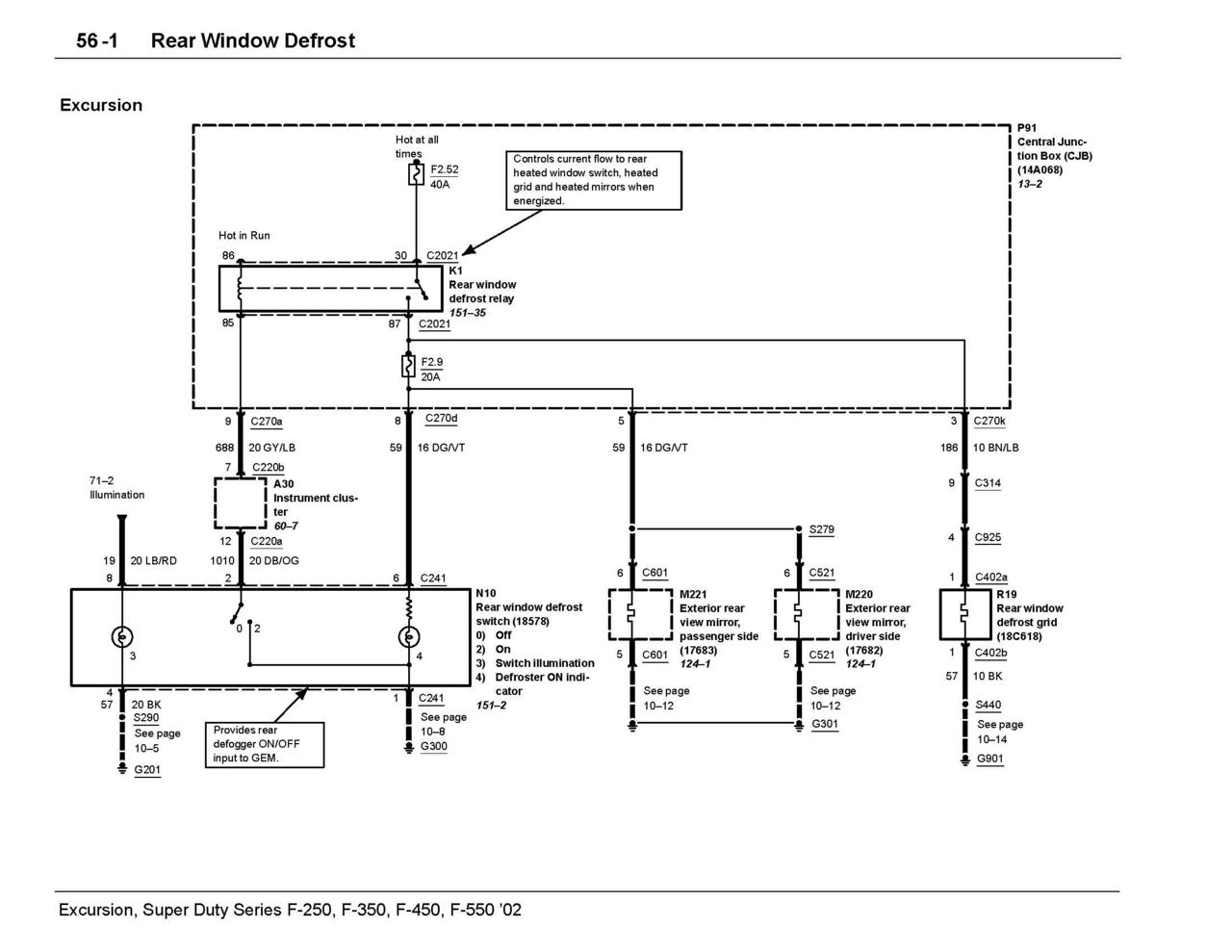
what is the defrost switch out of? It's a momentary switch and is usually negative triggered. light blue with red is illumination and there will also be a wire to power the switch LED.
I can try to post the defrost switch wiring from an excursion which is what I used for my heated mirrors. You cannot just wire it up and expect it to work though, it doesn't work that way. It's normally used to trigger a relay that is timer controlled by the PCM/ BCM
here's the wiring for an excursion defrost switch. I had to wire it differently to get it to work in my application but my brain may have not been working correctly too, hard to say
Not sure if you'll need this as well or if it will even help, but I also have this if needed
Rezvani's Latest Post-Apocalyptic Monster Is a Ford F-150 Raptor Underneath
Slideshow: Called the Fortress, the 850-horsepower pickup combines Raptor underpinnings with military-inspired features, survival equipment, and a starting price of $285,000.