When you click on links to various merchants on this site and make a purchase, this can result in this site earning a commission. Affiliate programs and affiliations include, but are not limited to, the eBay Partner Network.
There seem to be a number of members doing engine out work noted in various threads. And questions on fabricating the unique stands, lifting attachments and tools. But I figured it might be a good idea to consolotate what members do so we can share and provide a 'Best Practice' method, similar to what is done by SAE for vehicle design and testing.
I just purchased some Harbor Freight equipment, although I have to say I had to swallow hard to enter the store. But this is a garage, hopefully one time experience, so cost matters.
Ford, through Rotunda/Bosch has their own specialty tools, including the front frame attachment so the engine can come out the front of the vehicles, especially needed for the E vans. Looking at the design, it could be home built if you have good welding skills.
Lifting plates have been used both at garages and DIY, and in some cases allow the engine to come out carefully from under the hood with all of the cooler package and grill being removed.
Stands run the gammit from singular off the front or back, and both very expensive and DIY side mounts that allow for full access under any circumstance. Welding up the engine mounts will need to be done.
I've often said if I ever need to pull this motor I'll use my backhoe. I've used it to pull '65-66 Mustang 289s and it was ridiculously easy compared to engine cranes. We had two at my old facility. With the backhoe you have complete control in all directions hydraulically, it's a dream. Unfortunately for me at this time, it's 40 miles away.
So right now I have two Harbor Freight 1,000lbs stands sitting in their boxes to fab up a sidewinder style stand, and a Harbor Freight 2,000lb engine crane. These I selected based on reviewing threads about 6.0 rebuilding, and some vids on cranes. Admittedly, price was also a factor.
I need to have the motor out to layout my design for the stand mounting plates. Right now I'm envisioning using 3/8 angle iron bored for the block mounting hones, 2x2 or 2x3 square stock from the plates towards the stands, then a plate possibly to bolt to the stand existing plate. One of the unknowns right now is the positioning as I would like to have the position at the point of center of gravity both with and without the heads installed. This will change of course, so either two variables for stand mount or just a compromise inbetween.
Lifting plates for the top of the motor have been shown in multiple threads, and there's a guy on eBay who sells a fab'ed one specfic for the 6.0 for about $200. To me, that's a little high. I'm still contiplating what I want to do, I've seen people use the existing lift plates mounted on the heads as well. You can buy lifting rings that would fit in each of the block's pedestal mounting holes as well, each rated over 1,000lbs each, but lower when side loaded. Still thinking.
Some people have incorporated a worm and spur gear option for rotating the motor in the stand. When I looked at that option getting the components from McMaster it was expensive. With a worm gear setup the rotation would lock in place. Right now I'm looking at winch assemblies for the worm gear components that I could weld up or bolt up to the stands existing rotating axle. These axles already have locking holes to maintain positioning. So far the cheapest source I've found for a winch that may be viable is eBay:
I liked the technique of using a Forklift. When I used the backhoe for the first time I pulled a 289/auto combination out of a 'Stang I think I was giggling like a little girl. All the times I muscled an engine crane, fighting with floor seams, repositioning, ....
His stand is strong, made to be moved with Forklift. I need the wheels on the HF's, planning on an overtube on the center branch to connect the two.
The Norco is certainty a good commercial unit, and priced as such.
I figure I'll screw up the mounting plate angle which could bind the rotation axles, so I'm contemplating using the angle iron mounts, then a hitch pin through the angles and 2x2(3) so there is some movement to allow for this. The one thing I don't care for on the HF stands is the play between the axles and stand itself. Way looser then the stand I have a HiPo sitting on. Maybe an opportunity for some UHMW or other bearing insertion.
Preface: I was in a hurry, I am a crap welder, and I was using flux core wire (lots of splatter)
Here is how it came out:
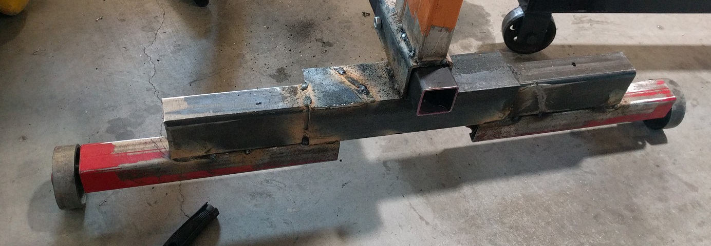
I started with 2 engine stands that I have from previous projects (I still have one more heavy duty one so no worries there).
Both of these stands were in the "I" formation like this (pic sourced from random amazon product):
Not sure where they came from but I know at least one was from harbor freight. One was orange, one was red.
First thing I did after disassembly, was cut the bottom part of the upright off square just above the square tube (this has a bit of square tube and angle iron welded to it). This is because they lean back a bit and you need them square.
I then went to work on the feet for the left and right side.
I measured the length of the engine and came to about 3 feet, so to keep the center of gravity so the stand doesn't tip I wanted to make each foot 3 feet long.
the non-swivel foot on the original stand was just over 2 feet long iirc so I cut it in half to expand it.
If you cut the angle iron off the center part of the "I" where it mounts to the swivel foot you end up with a nice piece of 2" square tube to weld on top of the two pieces you just made.
NOTE: I would highly recommend putting the fixed wheels towards the center of the stand as it helps with stability
This is where a steel supplier comes in. I bought the following from the remnant pile at my local steel house:
- 1 piece of 2" OD square tubing, at least 4 feet long, and at least 3/16 thick. Mine was 1/4"thick
- 1 piece of square tubing that is 2" ID so the previous tube can slide through it. you need a few feet of this. I found some 2.5" x 1/4" square tubing iirc
- 1 piece of 2" schedule 40 pipe, 4 feet long. this is to align the uprights and keep them square as you weld them on. it happens to have the right OD for the upper part of the uprights
- 1 piece of 3" x 1/4" angle iron... about 18" long more or less ( I had some scraps from another project)
To emulate the original stand design I welded the angle iron on top, centered.
Then after making sure everything was square I welded the 2.5" square tube on top of the angle iron (it was 6" long)
here is how that ended:
Put that aside for now.
Starting on the other foot I used the same idea except I used the top part of the "I" that had the swivels from each stand. Again, I used the middle part of the "I" with the angle iron cut off as the top piece.
Note: I did have to remove one of the inner wheels because they could hit each other.
here is how that came out:
Also note the reason for the lift is so that it fits over the cherry picker legs (thanks anthony for that idea).
There is one issue that I decided to ignore here... that is because of the design change, the left or drivers side foot is one inch lower than the swivel side. My plan to compensate for this is to get some solid wheels that are 2" larger in diameter for the left or fixed side of the engine stand. this will fix the slant. this also means you cant really use a level to do stuff unless you put 1" of steel under each of the fixed wheels. YMMV
MORE TO COME... I need to take care of something though...
OK... Continuing (I really should be working in the garage rather than typing btw)
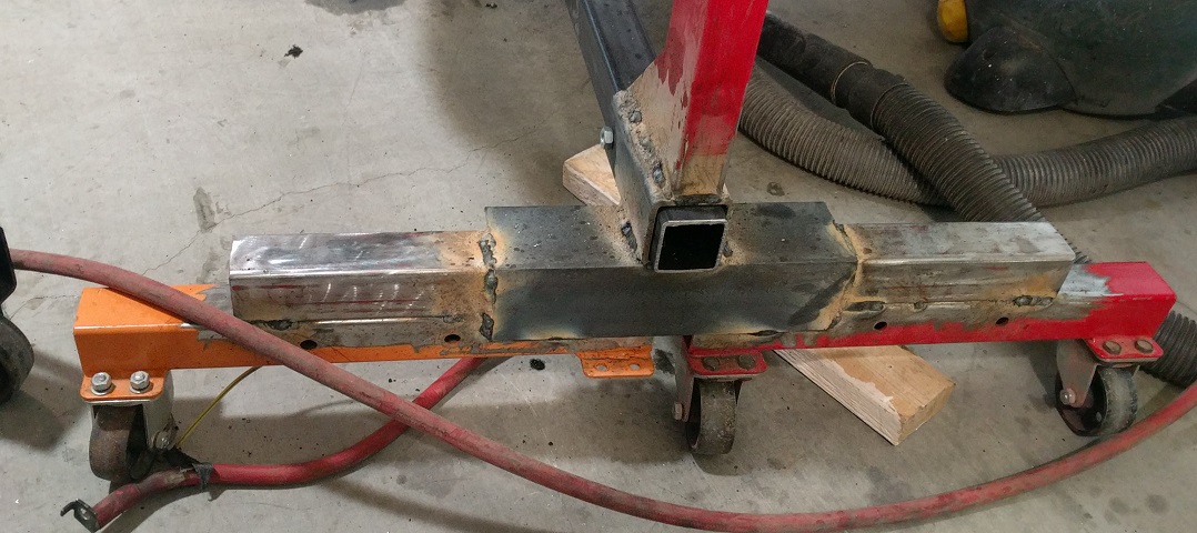
his is where I made a couple mistakes...
First. I slipped the square crossbar in and the Sch40 pipe in the uprights and welded. I had someone stand on the cross bar to align the feet.
What I should have done was have someone stand on the cross bar and then drill for the cross bolts this would have solved a issue I came across later with the engine mounts,
Anyway... go ahead and have someone stand on the cross bar and drill for the cross bolts. You could weld it but I wanted to be able to store it flatter. note that the cross bolts don't really have any stress on them so use whatever you have.
Once this is done put the sch40 pipe through the uprights and have a helper keep them square and aligned while you put a few tack welds on the base of the uprights.
You can check the gaps around the pipe to make sure it's all aligned... don't depend on the squareness of the cuts you made earlier.
and that is it for the main stand.
Now for the engine adapters...
For each engine adapter I used a piece of the 2.5" square tubing and 2 plates.
The engine plate was 1/4" thick. the stand side plate was 3/8 (again form the steel house's scrap bin.
I used a set of transfer punches (highly recommended) to transfer the hole from the engine mount bracket to the plate.
THE LEFT AND RIGHT MOUNTS ARE DIFFERENT! (yes I made that mistake)
a few things to check other than the above statement...
1.) make sure the bottom edge of the plate is high enough to clear the bedplate or you will never get it off. I think the thickness of the metal between the bottom hole and the bottom of the plate came out to 1/4-1/2".
you could weld spacers on the bottom like the above commercial plates but I didn't think of that and I was working with what I had.
2.) if you don't use the spacers you will have to notch the bottom of the plate to clear some bolt bosses.
Moving on... luckily the angle for the plates to the square tube is an even 45 degrees so it makes it easy to pre-cut.
I used the orignal engine stand brackets to draw on the 3/8 plate to make holes to bolt to the engine stand... if you wanted to you could skip that and cut a piece of sch40 pipe and weld to that.
But then you would have to drill holes for the safety pins and such and I decided it wasn't worth the time and effort.
I lowered the engine in the stand with the plates bolted to each side and got 11.5" from the bottom of the engine plate to the plate bolted to the engine stand upright.
so I cut 2 pieces of the 2.5" tubing at 45 degrees to that measurement and welded it to the engine plate.
Note that I did this with the heads and exhaust manifold on for a very good reason. I wanted some clearance (it came out to about 2") between the bottom of the manifold and the top of the square tube.
I also position the square tube to the rear of the engine plate, just barely forward of the rear two bolts so that the weld did not interfere with the flange bolts I got (m10 x 1.5 x 30mm iirc).
Once that was heavy tack welded to the engine plate I again lifted the engine in the engine stand to tack to the stand site plates.
This is where my earlier decision not to secure the center support tube bit me. because it was not secured the uprights had a slit tilt inward. Because I tacked it with the inward tilt, when I unbolted everything to burn in the welds, the angle between the square tube and the engine mount plate is not square and it forces that inward tilt. This adds resistance to rotating the engine.
Here is the important rotation that everyone seems to keep secret...
You want to center the rotation at the lower edge of the head gasket sealing surface and a hair to the rear front to back.
This will allow a relatively even center of gravity with the heads on i think. You could put the center a bit lower (up and down) if you wanted.
Feel free to ask any question or let me know if you want more measurements.
I weld soooooo infrequently I won't be showing my welds.
Thanks for including so many details. I saw the possible head angle issue to and was planning on a reweld to address that. I decided to purchase two stands of the same rather then dropping my other engine and try to match two since I had HF coupons. My steel supplier about five minutes from my house is going to see me often I believe. For awhile I was thinking of building from scratch.
Here's mine. I didn't do the welding (buddy @ welding shop next door did) it worked great. Moved my off set to the rear 3" I think. Was not hard to turn by hand. Engine lift goes under frame easy.
I used 1/2" steel plates for the engine mounts,,, 1/4" thick 3" square tubing for my mounts. I have put many full dress engines on mine. I have some modifications I've done over the years,, but the concept is the same. I absolutely love mine. It's strong as heck too.
Thanks for adding the vid Anthony. Before your text about it, I was thinking he's going to get sunburn on those legs. Me, I'll be setting my sneaker on fire.
Thanks for adding the vid Anthony. Before your text about it, I was thinking he's going to get sunburn on those legs. Me, I'll be setting my sneaker on fire.
Sometimes I don't think things thru. I remember waking up the next day saying "wtf is up with my leg?" Then I remembered. Lol
During my formal training I took more then expected courses about design with an instructor who was very Bauhaus oriented. So for me, form follows function, and the simplest, delicate designs structurally sound are beautiful creations. And little details such as the tube caps, as well as the motor attachment plates tell a story about the builder.
Here's another wife's "Only in your mind, Jack" utterance opportunity.


 . I will tell him. Had under $200.00 in materials not counting wheels.