


ignition wiring

Thread Starter
|
New User
Joined: Apr 2010
Posts: 6
Likes: 0
ignition wiring
Anybody have a ignition wiring Diagram for an 89 f350 dually.
I am trying to wire a toggle switch and push button start. I have searched through some back posts and what should be working is not?
Nice board here. Just bought a Ford after owning and still owning Dodge/Cummins
I am trying to wire a toggle switch and push button start. I have searched through some back posts and what should be working is not?
Nice board here. Just bought a Ford after owning and still owning Dodge/Cummins

Elder User
Joined: Apr 2002
Posts: 950
Likes: 2
From: West Bend
Would these be the ones you're after?
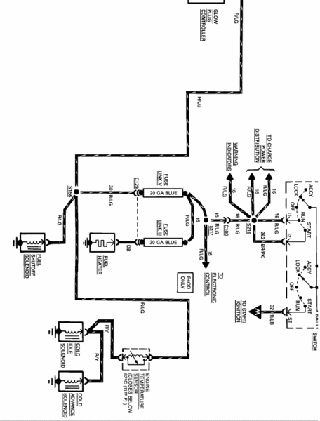

Man I gotta pay the 20 bucks so I can get 1024x768 res pictures! Big day for wiring diagram requests!
Chris
*EDIT* higher-res pictures mirrored on my site:
http://www.airplanesathome.com/FTEpics/Ign1.gif
http://www.airplanesathome.com/FTEpics/Ign2.gif
Man I gotta pay the 20 bucks so I can get 1024x768 res pictures!
Big day for wiring diagram requests!Chris
*EDIT* higher-res pictures mirrored on my site:
http://www.airplanesathome.com/FTEpics/Ign1.gif
http://www.airplanesathome.com/FTEpics/Ign2.gif
Last edited by swooshcmk; Apr 27, 2010 at 07:14 PM. Reason: added links to higher res pics
Thread Starter
|
New User
Joined: Apr 2010
Posts: 6
Likes: 0
OK.
Here lies the problem. I have 32 and 262 to a push button start.
Toggle is 16, 287 (Acc 2) and 297 (Acc 1)
However when the toggle is in the on position I get power in all the places I want.
However you push the clutch and the starter is turning over by passing the push button??
However 32 Should be the only power starter.
There should be no bypass as they all worked from the key before the tumblers broke.
Here lies the problem. I have 32 and 262 to a push button start.
Toggle is 16, 287 (Acc 2) and 297 (Acc 1)
However when the toggle is in the on position I get power in all the places I want.
However you push the clutch and the starter is turning over by passing the push button??
However 32 Should be the only power starter.
There should be no bypass as they all worked from the key before the tumblers broke.

Post Fiend
Joined: Nov 2003
Posts: 21,285
Likes: 16
From: Nutter Fort, WV

If you have 262 and 32 on the same terminal of the push button that is your problem.
Move them to separate terminals and you should be good to go.
Send power to 16 the red with green stripe wire and the engine will be ready to run and the batteries will be ready to charge when it starts.
When you turn the red with green stripe switch to on, 262 will supply power to the push button and when you push it, power will go to 32 and the engine will crank.
Where is 297 and 287?
All of the accessories operate when the key is on.
Only some of them operate when the key is in accessories, reverse lights for example only work when the key is in run position.
297 and 287 must be either the two groups of accesories or one of them is power in.
Move them to separate terminals and you should be good to go.
Send power to 16 the red with green stripe wire and the engine will be ready to run and the batteries will be ready to charge when it starts.
When you turn the red with green stripe switch to on, 262 will supply power to the push button and when you push it, power will go to 32 and the engine will crank.
Where is 297 and 287?
All of the accessories operate when the key is on.
Only some of them operate when the key is in accessories, reverse lights for example only work when the key is in run position.
297 and 287 must be either the two groups of accesories or one of them is power in.

Postmaster
Joined: Dec 2002
Posts: 3,594
Likes: 2
From: Southern Oregon USA
I'm going off of an 89 diagram with no circuit numbers and a 93 diagram with them. Should be pretty similar though.
The 12V supply for your push button and both ACC and RUN switches should come from the Yellow wire (ckt 38) This is the way that the factory switch is wired. Doing it this way would allow the starter button to function at any time regardless of whether the toggles are on, which isn't a big deal. It won't work unless the clutch is depressed anyways.
I don't think 262 should be needed at all with separate switches. With the original switch, it supplies 12V to ckt 16 only while cranking. If the RUN toggle is on, it will already be doing that.
Jason
The 12V supply for your push button and both ACC and RUN switches should come from the Yellow wire (ckt 38) This is the way that the factory switch is wired. Doing it this way would allow the starter button to function at any time regardless of whether the toggles are on, which isn't a big deal. It won't work unless the clutch is depressed anyways.
I don't think 262 should be needed at all with separate switches. With the original switch, it supplies 12V to ckt 16 only while cranking. If the RUN toggle is on, it will already be doing that.
Jason
Thread Starter
|
New User
Joined: Apr 2010
Posts: 6
Likes: 0
Thanks to everyone.
I had the 32 and the 262 on the same terminal. Thus the continued start.
this is how I have it wired and it works.
Push button 262 one terminal the other terminal is 32, 977(p1) and 41(p2)
I don't need any acc 2 on the toggle. As I have a flatbed and I am gonna wire flood lights the reverse lights. And I did not want to mess with it for only the radio and cig lighter!
So on the single switch is the power on one terminal (both yellow) and the other contains the 16(11), 687 (a2), and 297 (a1).
It all works so far. sound right?
Next question is which one affects the glow plug controller relay? With the key I could here it "Clicking". Now I am getting no click at all and very hard start. I am trying to diagnose my bad wiring or bad controller or plugs.
I had the 32 and the 262 on the same terminal. Thus the continued start.
this is how I have it wired and it works.
Push button 262 one terminal the other terminal is 32, 977(p1) and 41(p2)
I don't need any acc 2 on the toggle. As I have a flatbed and I am gonna wire flood lights the reverse lights. And I did not want to mess with it for only the radio and cig lighter!
So on the single switch is the power on one terminal (both yellow) and the other contains the 16(11), 687 (a2), and 297 (a1).
It all works so far. sound right?
Next question is which one affects the glow plug controller relay? With the key I could here it "Clicking". Now I am getting no click at all and very hard start. I am trying to diagnose my bad wiring
or bad controller or plugs.

Post Fiend
Joined: Nov 2004
Posts: 5,638
Likes: 1
From: Manitoba
FYI the solid state system your circumventing is almost foolproof.......... why do you want to do that.
All you had to do was put a pushbutton on the ground wire to the controller and let it operate normally until "You" wanted it to stop by releasing the button.
All you had to do was put a pushbutton on the ground wire to the controller and let it operate normally until "You" wanted it to stop by releasing the button.
Trending Topics
Thread Starter
|
New User
Joined: Apr 2010
Posts: 6
Likes: 0
I agree.
I want to leave the gp system stock. The only system I am bypassing should be the ignition switch.
I want to leave the gp system stock. The only system I am bypassing should be the ignition switch.
FTE Stories
Ford Trucks for Ford Truck Enthusiasts

Top 6 Best Deals Available on New Fords & Lincolns Right Now
Brett Foote
This Hennessey Takes the Expedition Tremor's Off-Roading Capability to the Next Level
Verdad Gallardo
Top 10 Fords at 2026 Carlisle Ford Nationals
Joe Kucinski
3 Best / 3 Worst Parts of Modern Ford Ownership
Brett Foote
10 Amazing Upgrades That Solve Common Ford Truck Owner Headaches
Pouria Savadkouei
Every 2026 Ford Engine Explained
Brett Foote
10 Ugly Ford Trucks That We Still Kinda Love
Joe Kucinski
10 Things Every Truck Owner NEEDS (2026 Edition)
Michael S. Palmer
Rezvani's Latest Post-Apocalyptic Monster Is a Ford F-150 Raptor Underneath
Verdad Gallardo
Postmaster
Joined: Dec 2002
Posts: 3,594
Likes: 2
From: Southern Oregon USA
That sounds correct.
Since you have done some wiring modification at the ign switch, I would start with making sure you have not blown a fuse or burned a fusible link. At the controller, you should have Key On 12V at the blue wire (ign feed, from ckt 16). Batt 12V at the yellow wires (from starter relay batt terminal, through fuse links. You should have a steady ground signal from the black/pink until the controller starts the afterglow cycling. Then it will cycle with the WTS light. There will be a fuse for the WTS light as well.
A common problem is the controller ground.
Check glow plugs by disconnecting the terminals to them. Hook your test light clamp to batt + and touch each glow plug. Test light on means a good glow plug.
Jason
Since you have done some wiring modification at the ign switch, I would start with making sure you have not blown a fuse or burned a fusible link. At the controller, you should have Key On 12V at the blue wire (ign feed, from ckt 16). Batt 12V at the yellow wires (from starter relay batt terminal, through fuse links. You should have a steady ground signal from the black/pink until the controller starts the afterglow cycling. Then it will cycle with the WTS light. There will be a fuse for the WTS light as well.
A common problem is the controller ground.
Check glow plugs by disconnecting the terminals to them. Hook your test light clamp to batt + and touch each glow plug. Test light on means a good glow plug.
Jason
Post Fiend
Joined: Nov 2003
Posts: 21,285
Likes: 16
From: Nutter Fort, WV
Just figured something out.


With the links reversed, the pics above go together and make one large diagram.
You should already have ignition power at the glow plug relay.
When the key is on, power to the red wire small ignition terminal.
Same wire sends power to the fuel shut off solenoid.

Also the battery terminal should have power at all times.
With the links reversed, the pics above go together and make one large diagram.
You should already have ignition power at the glow plug relay.
When the key is on, power to the red wire small ignition terminal.
Same wire sends power to the fuel shut off solenoid.
Also the battery terminal should have power at all times.

Thread
Thread Starter
Forum
Replies
Last Post
jdhudall
1973 - 1979 F-100 & Larger F-Series Trucks
24
May 19, 2017 10:55 AM
wavetrain75
1948 - 1956 F1, F100 & Larger F-Series Trucks
6
Dec 21, 2016 12:23 PM
StoneHarding
1973 - 1979 F-100 & Larger F-Series Trucks
1
Jul 10, 2016 11:00 AM
