


Need help wiring ammeter
Thread Starter
|
Freshman User
Joined: Jan 2010
Posts: 25
Likes: 0
From: Madison Wi.
I have a 59 F100 & am trying to wire in an ammeter & need some help the ammeter came with 8 different diagrams i do not know which before diagram i have could some one tell me the easiest way to wire this up  any info would be appreciated Thanks i have not had a chance to get a manual for this yet only had this truck about a week & am moving so would like to have everything working properly for the long road trip Thanks again
any info would be appreciated Thanks i have not had a chance to get a manual for this yet only had this truck about a week & am moving so would like to have everything working properly for the long road trip Thanks again
Cargo Master


Joined: Feb 2008
Posts: 2,793
Likes: 128
From: Windermere Valley,B.C. Ca

Is this aftermarket or stock? 
If aftermaket don�t, ��a true ammeter measures all the power (except starter) going in and out of the charging system, (read arc welder, sparks and fire), install a voltmeter, gives same info , one switched hot wire (from ign) , one ground, little electrical draw.

If aftermaket don�t, ��a true ammeter measures all the power (except starter) going in and out of the charging system, (read arc welder, sparks and fire), install a voltmeter, gives same info , one switched hot wire (from ign) , one ground, little electrical draw.
Hotshot
Joined: Jan 2010
Posts: 10,060
Likes: 491
From: Bristol, TN.
When I install ammeters they come with a shunt so wire size to meter can be very small and still be very accurate. Doing the installation this way is very safe i.e no arc welding, although I understand what you are saying without a shunt. Of course, I have no idea what came with the one above.
Steve
Steve
Thread Starter
|
Freshman User
Joined: Jan 2010
Posts: 25
Likes: 0
From: Madison Wi.
ok the gauge is a suntune amps -60 to +60 it has two posts on the back A + & a - the instructions has 8 different before diagrams & 8 coresponding after diagrams i figured it was a simple as always hot from ign to + side of gauge & the hot side of gen to + side of gauge then - side of gauge to + side of batt but when i went to connect batt up arc welding started to occure to batt post & term does this help?? what did i do wrong??

Post Fiend
Joined: May 2008
Posts: 7,641
Likes: 21
From: Poway, Ca.
No, not quite. In the Ford wiring flow you should have power being supplied by the generator which flows down to the power distribution point (fuse panel, circuit breaker or what ever). From there power should flow up to the ignition switch "BATT" terminal then back out to the "BATT" post of the starter solenoid.
You want to wire your gauge on the wire that goes out to the "BATT" post of the starter solenoid from the last point (farthest from the generator regulator) power is distributed - probably the ignition switch. On a 12 volt negative ground vehicle you want the end of the wire coming down from the solenoid to connect to the positive post of the gauge. Then the negative post of the gauge connects to the continuation of that wire downline to the "BATT" terminal of your ignition switch or whatever distribution point it continues down to.
In other words you have power flowing in one of two directions from the generator through the electrical distribution then on to the battery (when the generator is working - ie charging) or down from the battery to the electrical distribution (when the generator is not working - ie discharge). Yo want to wire the gauge onto the wire that is closest in that flow to the starter solenoid.
Check me on that RV-TECH!
Thread Starter
|
Freshman User
Joined: Jan 2010
Posts: 25
Likes: 0
From: Madison Wi.
Ok let me repeat what you said to make sure i got it its a 12 v neg ground. ok it sounds like i need to connect to the power feed to the starter solenoid & the + side of the gauge, then connect the - side of the gauge to the always hot side of the ignition. correct so i should only need two wires? the gauge should be in series correct? let me know if i got it. Thanks for your help Julie
Trending Topics
Post Fiend
Joined: May 2008
Posts: 7,641
Likes: 21
From: Poway, Ca.
It's hard to put into words. Here's a picture of my 51 wiring scheme and what I was trying to describe. The little circle with the "amp" is the ammeter.
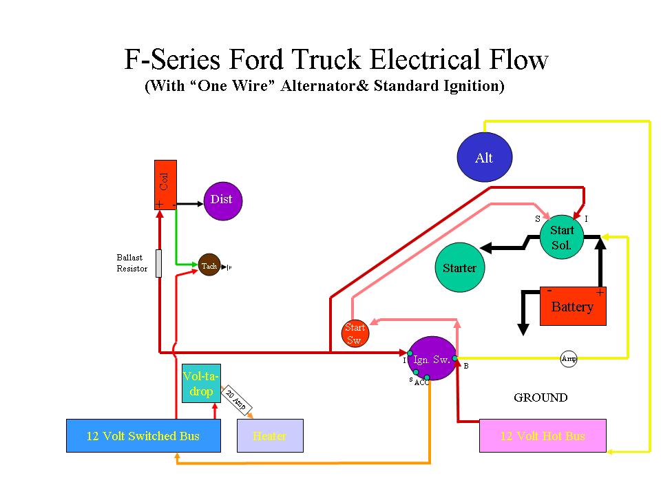
The "BUS" is a fuse box or whatever your truck uses to distribute electricity out to your accessories. Hot bus is powered all the time for lights, horn, brake lights, door/courtesy lights, etc. Switched bus powers heater, wipers, radio, etc, all the things that get turned on with the ignition.
Use the shunt that RV recommended. It should be mentioned in the instructions and included in the kit.
FTE Stories
Ford Trucks for Ford Truck Enthusiasts

10 Best Ford Truck Engines We Miss the Most!
Joe Kucinski
2026 Shelby F-150 Off-Road: Better Than a Raptor R?
Brett Foote
2027 Super Duty Carhartt Package First Look: 12 Things You NEED to Know!
Michael S. Palmer
10 Most Surprising 2026 Ford Truck Features!
Joe Kucinski
Top 10 Ford Trucks Coming to Mecum Indy 2026
Brett Foote
5 Best / 5 Worst Ford Truck Wheels of All Time
Joe Kucinski
Ford Super Duty: 5 Things Owners LOVE, 5 Things They LOATHE!
Joe Kucinski
Every 2026 Ford Truck Engine RANKED from WORST to FIRST!
Michael S. Palmer
The Best F-150 Deal of Every Trim Level (XL through Raptor)
Joe KucinskiThread Starter
|
Freshman User
Joined: Jan 2010
Posts: 25
Likes: 0
From: Madison Wi.
I dont have the shunt & the instructions do not mention any thing about it. i will wait till i get moved & pick up a volts gauge also i have a three wire generator hot ground & field the gauge was in the truck but never fully installed.so i will wait till i have more time on my hands Thanks for all your help.
Hotshot
Joined: Jan 2010
Posts: 10,060
Likes: 491
From: Bristol, TN.
It's hard to put into words. Here's a picture of my 51 wiring scheme and what I was trying to describe. The little circle with the "amp" is the ammeter.
Attachment 20234
The "BUS" is a fuse box or whatever your truck uses to distribute electricity out to your accessories. Hot bus is powered all the time for lights, horn, brake lights, door/courtesy lights, etc. Switched bus powers heater, wipers, radio, etc, all the things that get turned on with the ignition.
Use the shunt that RV recommended. It should be mentioned in the instructions and included in the kit.
I am impressed with your wiring schematic, but am curious. Have you ever compared you amp meter reading to the reading on a clamp-on meter at the battery cable? I always think in terms of wiring an amp meter in series with the battery (never good) or else using a shunt, but I have never tried to hook one up in your application. Again,, just a question, not a shot. I have to study this one as it is new to me.
Steve
Post Fiend
Joined: May 2008
Posts: 7,641
Likes: 21
From: Poway, Ca.
I haven't measured the gauge for accuracy to be quite honest. I'm simply interested in it indicating whether or not the alternator is working. I have a one wire alternator and it's kind of like a light switch, it's either working (and it works properly when it is) or it doesn't work. And my gauge is very "obvious" in letting me know if I have an charging system casualty. And I have a way to confirm it as well when driving.
My amp guage usually indicates a slight charge while running normally (after the start up pulse etc) and if it stops it definately slips back to the mid position. But I have FOUR large stock 6 volt trumpet horns on my 12 volt system and with the amperage draw they pull, if the alternator is not working, they won't even sound.
I had an experience with this because when I wired the truck I mixed up my spool of 12 gauge wire up with my 10 gauge wire and by mistake wired the main charge wire with 12 gauge (on a 100 amp alternator - yeah, what a moron). Anyway after about 8K miles, it crispied the connector on the back of the alternator and wasn't making good enough contact to charge.
So I replaced the wire with a piece of 8 gauge and fixed the connector.
I really don't have enough running all the time to come anywhere close to pushing a 100 amp alternator. At most on a rainy night, I will run lughts, heater/defrost, and wipers with out a hitch. So I really haven't been that worried about the amount of amps being put out, only that there are amps being put out.
This particular wiring scheme follows the original electrical flow path in the F-series and F-100s (up to 56) that used the induction loop meter as a flow direction sensor.
I've found that wiring a true ammeter depends largely on both your power distribution and your charging system. If you have a simple one wire like mine, this works. If youhave a one wire that needs an exciter, this may not. If you are using an external regulator or generator this should work as well. It also depends on whether or not you are replacing an idiot light and if that idiot light acts as an exciter. So there's all kinds of configurations.
That's probably why our friend has discovered the 8 different wiring diagrams.
But, I see no reason why the am meter could not be hooked up this way. I think it depends on the gauge too. That's why I asked you to look at my diagram since you tend to do this more regularly.
Hotshot
Joined: Jan 2010
Posts: 10,060
Likes: 491
From: Bristol, TN.
Hi Julie,
I was sure your schematic would indicate a charge. I am always dealing with needing to know the exact output, so my needs are different than yours and it is not unusual for me to be measuring 100-200 amp output from chargers and alternators. I was just curious.
Steve
I was sure your schematic would indicate a charge. I am always dealing with needing to know the exact output, so my needs are different than yours and it is not unusual for me to be measuring 100-200 amp output from chargers and alternators. I was just curious.
Steve
Post Fiend
Joined: May 2008
Posts: 7,641
Likes: 21
From: Poway, Ca.
Yep, I understand completely.
And that's a good point for Vato to remember. If you really need to measure amps - either because you have a high draw or you need to protect things, then you will need a good gauge that measures that amount accurately.
But in most applications, just simply to know that th echarging system is online and satisfying the demand is enough. Hey Vato, are you replacing an idiot light or does your truck have an actual gauge you are replacing? If you have the gauge already, it will be an induction loop type and easy to work with. If you have an idiot light, can you find a stock gauge or even a face to put on an induction loop type? Much simpler and safer - if you don't need the measurement.
Thread Starter
|
Freshman User
Joined: Jan 2010
Posts: 25
Likes: 0
From: Madison Wi.
what i was doing is using the ammeter cause it came with the truck in a three cluster set with temp,& oil pressure so i was gonna replace the light with it. I had to replace the original fuel gauge & sender & when i got the fuel gauge i got lucky & the wiring diagram for the sun pro Fuel gauge came it had all of there gauges in it with instructions & the sunpro & Suntune gauges are from actron mfg. so since i had the instructions i thought i would hook it up. By the way what is a shunt?? I am not an electrical wizard yet.workin on it. I think what i will do is wait till i get moved & get a manual for a 59 F100 & go from there or i may just put a volt gauge in mainly just want to know that im charging & a volt gauge should give me enough indication of that Thanks to both you for all the help. Thanks

Elder User
Joined: Jun 2008
Posts: 693
Likes: 6
From: N E Ohio
From what I have seen, Sunpro ammeters do not use an external shunt, they are wired directly into the circuit. As you have a 59, if you have the original style generator it is probably not more than 40 amps, so wiring in the ammeter is not that big of a deal. To measure current into and out of the battery I would find the starter relay (pass side inner fender) and start there. The cable from the battery + goes to one terminal of this relay. There are also several smaller wires attached to this same terminal.
1. Disconnect battery - cable
2. remove nut from the relay terminal the battery + cable goes to.
3. remove battery + cable.
4. remove other wires from this terminal, and using a bolt and nut attach them to a 10 gauge minimum wire with a ring terminal on it. Tape this up real well and connect the other end of this wire to the - terminal of the ammeter.
5. Connect another 10 gauge minimum wite to the + terrminal of the ammeter. Run this wire back to the starter relay, and put it on the terminal the battery + cable originally was. I like to use a copper sleeve crimp style ring connector on this wire.
6. Reconnect the battery + cable to the terminal on the starter relay you originally removed it from, and reinstall the nut.
7. Make sure that you insulate and cushion the two new wires to the ammeter where they go through the firewall.
8. Reconnect the battery - cable
9. Turn on the headlights, the ammeter needle should swing to the - (discharge) side, if not, disconnect the battery - cable and reverse the wires at the ammeter. Reconnect battery - cable and try again.
This should do it. If you have a high current generator, or an alternator with more than a 40 amp output you will need wires heavier than 10 gauge.