


windstar Air Bag codes....
Post Fiend
Joined: Apr 2005
Posts: 5,720
Likes: 5
From: Washington state
when manuf.'s quit producing a vehicle model, they should be required to post all the service information on their web site open to the public.
too much model unique information making service almost impossible. most dealer shops refuse to work on anything older than 5 years.
should be considered part of original purchase.
too much model unique information making service almost impossible. most dealer shops refuse to work on anything older than 5 years.
should be considered part of original purchase.

Thread Starter
|
Post Fiend
Joined: Oct 2005
Posts: 5,242
Likes: 0
From: Kiev, Ukraine
well, I read about this Air Bag Codes - '93 Taurus GL 3.0 - Ford Forums - Mustang Forum, Ford Trucks and Cars
I have one more AB unit home.
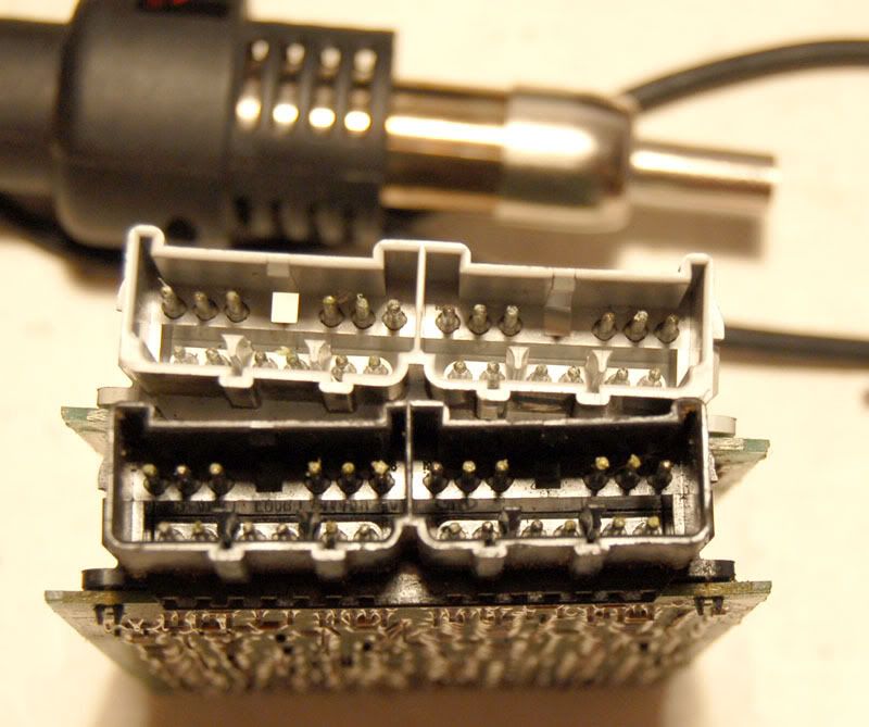
unit I have with black conector, unit from windstar (2 air bags) with gray connector.

I cant locate thermal fuse, I can see rectifiers, Zener diodes, some chips I cant get datasheet for. I'm not sure about its compatibility, I used to think to swap them.
Well, connectors differ a bit too. So I'm not sure.
Any tips friends..... ????
I have one more AB unit home.
unit I have with black conector, unit from windstar (2 air bags) with gray connector.
I cant locate thermal fuse, I can see rectifiers, Zener diodes, some chips I cant get datasheet for. I'm not sure about its compatibility, I used to think to swap them.
Well, connectors differ a bit too. So I'm not sure.
Any tips friends..... ????
Thread Starter
|
Post Fiend
Joined: Oct 2005
Posts: 5,242
Likes: 0
From: Kiev, Ukraine
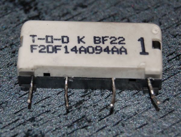
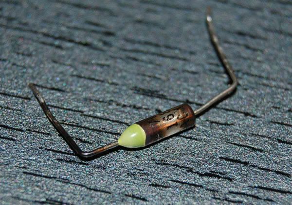
well, I soldered out fuse. it is a small box with 15 ohm resistor and fuse inside. when resistor is hot fuse blows.
Trending Topics
Thread Starter
|
Post Fiend
Joined: Oct 2005
Posts: 5,242
Likes: 0
From: Kiev, Ukraine
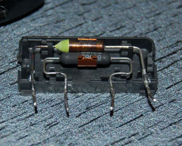
But, I cant read what the temperature this fuse must blow.
Before the fuse blown we had code 13. As I've understood it is intermediate short to ground of AB actuating circuits, so before changing this fuse I have to locate 617 ore 624 wire damage, else I will get blown fuse againe.
well, I have no AB code list and fuse specification.
FTE Stories
Ford Trucks for Ford Truck Enthusiasts

Top 10 Fords at 2026 Carlisle Ford Nationals
Joe Kucinski
3 Best / 3 Worst Parts of Modern Ford Ownership
Brett Foote
10 Amazing Upgrades That Solve Common Ford Truck Owner Headaches
Pouria Savadkouei
Every 2026 Ford Engine Explained
Brett Foote
10 Ugly Ford Trucks That We Still Kinda Love
Joe Kucinski
10 Things Every Truck Owner NEEDS (2026 Edition)
Michael S. Palmer
Rezvani's Latest Post-Apocalyptic Monster Is a Ford F-150 Raptor Underneath
Verdad Gallardo
Top 10 Most Expensive Ford Trucks Ever Sold on Bring a Trailer
Joe Kucinski
2027 Ford Super Duty Buyer's Guide (Every Model, Engine, & Package)
Brett Foote
Thread Starter
|
Post Fiend
Joined: Oct 2005
Posts: 5,242
Likes: 0
From: Kiev, Ukraine
Update: I'm not the first.... may be clockspring is bad..... https://www.ford-trucks.com/forums/1...ag-module.html
Thread Starter
|
Post Fiend
Joined: Oct 2005
Posts: 5,242
Likes: 0
From: Kiev, Ukraine
Update:
| 12 Low Battery Voltage
| 13 Air Bag Circuit or Crash Sensor Circuit - Shorted to Ground
| 21 Safing Sensor - Not Mounted on Vehicle Properly
| 22 Safing Sensor Output Circuit - Shorted to Battery Voltage
| 23 Safing Sensor Input Feed/Return Circuit Open
| 24 Open in Circuit 944B or Low Resistance in Crash Sensor(s)
| 32 Driver Side Air Bag/Safing Sensor Circuit - High Resistance or Open
| 33 Pin 7 Not Grounded at Diagnostic Monitor
| 34 Driver Side Air Bag/Safing Sensor Circuit - Low Resistance or Shorted
| 35 Low Resistance Across Pins 8 and 9 at Diagnostic Monitor
| 41 Crash Sensor Circuit - High Resistance or Open
| 44 RH Crash Sensor - Not Mounted to Vehicle Properly
| 45 Center Radiator Crash Sensor - Not Mounted to Vehicle Properly
| 46 LH Crash Sensor - Not Mounted to Vehicle Properly
| 51 Diagnostic Monitor Internal Thermal Fuse - Blown and Short to Ground No Longer Exists
| 52 Backup Power Supply - Voltage Boost Fault
| 53 Internal Diagnostic Monitor Fault
so what to check first? clockspring ore crash sensor?
Post Fiend
Joined: Apr 2005
Posts: 5,720
Likes: 5
From: Washington state
168d C
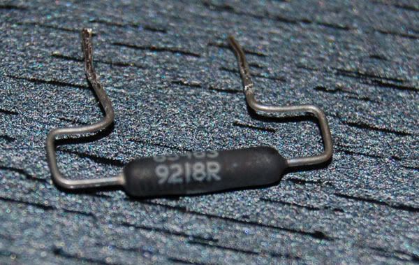
I would also check the resistance of the resistor, they often change value under high heat and high current
crash sensor and it's wiring are easier to test
i would not even bother testing an old clockspring, probably intermittent and will just short out again when cranked the offending direction.
new is cheaper in the long run time and headache wise.
might end up with both air bags going boom when making a quick lane change on the freeway at 70mph.
Thread Starter
|
Post Fiend
Joined: Oct 2005
Posts: 5,242
Likes: 0
From: Kiev, Ukraine
clockspring change..... how to? I used to change it on mercedes trucks. it is intgegrated into steering wheel angle sensor. I had to pull steering wheel, so on ford I have to remove dr.side air bag and replace old clockspring
Post Fiend
Joined: Apr 2005
Posts: 5,720
Likes: 5
From: Washington state
dont' turn that WindLessStar into another Chernobyl


WARNING: THE BACK UP POWER SUPPLY ENERGY MUST BE DEPLETED BEFORE ANY AIR BAG COMPONENT SERVICE IS PERFORMED. TO DEPLETE BACK UP POWER SUPPLY ENERGY, FIRST DISCONNECT THE BATTERY GROUND CABLE (14301), THEN DISCONNECT THE POSITIVE BATTERY CABLE AND WAIT ONE MINUTE TO AVOID ACCIDENTAL DEPLOYMENT AND POSSIBLE PERSONAL INJURY.
NOTE: When the battery (10655) has been disconnected or reconnected, some abnormal drive symptoms may occur while the powertrain control module (PCM) (12A650) relearns its fuel trim. The vehicle may need to be driven 18 km (10 miles) or more to relearn the fuel trim.
NOTE: When the battery has been disconnected or reconnected, volatile memory information will be lost. The affected systems will have to be programmed by the technician or customer. These systems include radio station presets, clock settings, seat memory, window memory and customer input keyless entry codes.
Removal
WARNING: THE BACKUP POWER SUPPLY MUST BE DISCONNECTED BEFORE ANY AIR BAG COMPONENT IS SERVICED TO PREVENT ACCIDENTAL AIR BAG DEPLOYMENT.
Center front wheels to the straight-ahead position.
Disconnect battery ground cable (14301). Refer to Section 14-01 .
Pry out two steering wheel spoke covers (3L518) covering air bag module screws on sides of steering wheel (3600).
Remove two air bag module retaining screws on side of steering wheel from driver side air bag module (043B13) and lift driver side air bag module away from steering wheel.
Disconnect air bag wire harness connector, horn control wire harness connector, and, if equipped, speed control harness connector.
CAUTION: Be sure both air bag sliding contact assembly wire harnesses do not get caught on steering wheel when lifting steering wheel off of steering shaft to prevent damage.
Remove steering wheel retaining bolt. Discard retaining bolt.
Install Steering Wheel Puller T67L-3600-A and remove steering wheel. Route contact assembly wire harness through steering wheel as steering wheel is lifted off steering shaft.
CAUTION: Be sure air bag sliding contact internal service lock is engaged. Air bag sliding contact (14A664) should not be turned more than 45 degrees to the right or left to prevent damage.
Rotate air bag sliding contact to the right or left to engage service lock.
Installation
Make sure the vehicle's front wheels are in the straight-ahead position.
CAUTION: Be sure wiring does not get trapped between steering wheel and air bag sliding contact or air bag monitor will detect a fault.
Route air bag sliding contact wire harnesses through steering wheel opening at the three o'clock position. Position steering wheel on steering shaft so the alignment marks are aligned. Be sure air bag contact wire is not pinched.
Install new steering wheel retaining bolt and tighten to 34-46 Nm (25-34 lb-ft).
Connect horn/speed control wire harness to air bag sliding contact wire harness.
Connect air bag wire harness and horn wire harness from air bag sliding contact to driver side air bag module and install module to steering wheel. Make sure all air bag-to-steering wheel seams are flush and no gaps visible.
Tighten air bag sliding contact retaining screws to 12 Nm (106 lb-in); then insert two steering wheel spoke covers.
Connect battery ground cable. Verify air bag warning indicator.
Steering Wheel with Air Bag
Item Part Number Description
1 043B13 Driver Side Air Bag Module
2 N804385-S100 Screw
3 N606676-S36 Screw
4 3L518 Steering Wheel Spoke Cover
5 14A664 Air Bag Sliding Contact
6 3600 Steering Wheel
A � Tighten to 36-46 Nm (25-34 Lb-Ft)
B � Tighten to 2-3 Nm (18-27 Lb-In)
Sliding Contact, Air Bag
Removal
WARNING: THE BACKUP POWER SUPPLY MUST BE DISCONNECTED BEFORE ANY AIR BAG COMPONENT IS SERVICED TO PREVENT ACCIDENTAL AIR BAG DEPLOYMENT.
Make sure that vehicle's front wheels are in the straight-ahead position and steering column shaft alignment mark is at the 12 o'clock position.
Disconnect battery ground cable (14301). Refer to Section 14-01 .
Remove steering wheel (3600) as outlined.
CAUTION: Be sure air bag sliding contact internal lock is engaged. Hub should not turn more than 45 degrees in either direction to prevent damage.
Remove steering column upper and lower steering column shrouds (3530) as outlined in this section.
Disconnect three air bag sliding contact electrical connectors from main wiring harness at steering column instrument panel bracket (3676).
CAUTION: Do not remove wire harness clips from wire bundle to prevent damage.
Using door trim removal tool, remove air bag sliding contact electrical connectors from bend bracket.
Using door trim removal tool, disconnect two wire harness clips from column.
Remove key warning buzzer contact and anti-theft contact from ignition lock cylinder pocket of steering column lock cylinder housing (3511).
Remove air bag sliding contact (14A664) by pushing snap back at 6 o'clock position first, then 3 o'clock position, then 12 o'clock position and remove from steering shaft.
Installation
Make sure that the vehicle's front wheels are straight ahead and steering column shaft alignment mark is at the 12 o'clock position.
Align air bag sliding contact to column shaft and mounting tabs and slide onto shaft. Push on air bag sliding contact to snap three tabs onto steering column lock cylinder housing.
Install air bag sliding contact cable clips into holes in steering column.
Install air bag sliding contact connector retainers into provided holes in steering column bend bracket.
Plug main wiring harness connectors into three air bag sliding contact connectors.
Install key warning buzzer contact and anti-theft contact into ignition lock cylinder pocket in steering column lock cylinder housing. Make sure contacts do not slip out of ignition lock cylinder pocket.
Install upper and lower steering column shrouds as outlined in this section.
Install steering wheel as outlined in this section.
Connect battery ground cable. Refer to Section 14-01 .
Verify air bag warning indicator operation.
Steering Wheel With Air Bag
Item Part Number Description
1 16043B13 Driver Side Air Bag Module
2 N804385-S100 Screw
3 N606676-S36 Screw
4 3L518 Steering Wheel Spoke Cover
5 14A664 Air Bag Sliding Contact
6 3600 Steering Wheel
A � Tighten to 36-46 Nm (25-34 Lb-Ft)
B � Tighten to 2-3 Nm (18-27 Lb-In)
Thread Starter
|
Post Fiend
Joined: Oct 2005
Posts: 5,242
Likes: 0
From: Kiev, Ukraine
so there is no clockspring there but sliding contact.... so first of all I should find what a circuit is short, becouse I got 13 code before 51. As I've understood airbag system of windstar is like in taurus. well, checking wires with AVOmeter have I risk to actuate air bags?

Thread
Thread Starter
Forum
Replies
Last Post
air, airbag, airbagsafing, bag, circuit, diagnostic, driver, ford, light, low, maintenance, monitor, resistance, sensor, shorted, side, windstar