When you click on links to various merchants on this site and make a purchase, this can result in this site earning a commission. Affiliate programs and affiliations include, but are not limited to, the eBay Partner Network.
I have tons of wiring diagrams. But, I would need to know the specifics of what you want and your current set up.
There is a wiring diagram in the back of your shop manual by the way.
So, just a few questions: Are you still running 6 volt positive ground. Are youstill using the stock circuit breakers (those two butter cube shaped things bolted to the instrument panel) for power distribution?
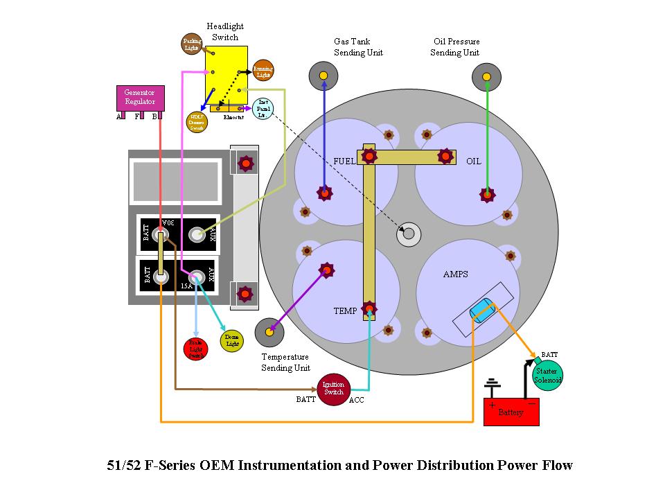
If so, then the power to the gauges runs over from the "AUX" stud on the 15 amp breaker to the in side of the Temp gauge. There should be a metal shunt connecting the power post on the temp gauge to the power post on the gas gauge and the power post on the oil pressure gauge.
From the other stud on each gauge a wire travels out to the appropriate sending unit.
For your amp guage, a wire runs from the "Batt" end of the 15 amp circuit breaker, through the induction loop on the back of the gauge to the "Batt" terminal of the starter solenoid.
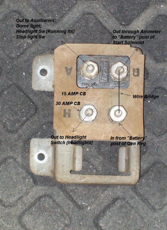
Just FYI, the "Batt" post of the 30 amp circuit breaker accepts the wire from the "Batt" terminal on your Generator Voltage Regulator and also has a metal shunt (bridge) to the "Batt" post on the 15 amp breaker.
A few pics...note the metal power shunt on the gauges. Run power to any one of these studs. The unoccupied ones connect to the wires that go out to the sending units.
Let me know if you need more or if you are converting to 12 volt.
This is OEM signal flow (colors of lines are not colors of wires).
Also note: The gauges in the picture and the diagram are flipped top to bottom as if you turned the assembly over in your hand - Amp and Temp guage are on top when mounted in the vehicle and Circuit Breakers are still on the left.
I didn't get back in time to make one small change to the diagram above. The brown line coming off the "AUX" side of the 30 Amp breaker that goes to the "BAT" post of the ignition switch, actually comes off the "BAT" side of that breaker. Like this:
Thats a cool diagram. This will make alot of people happy.Just one more question. When I switch to 12v I would put the reducer after the ignition switch on the acc. wire?
Thats a cool diagram. This will make alot of people happy.Just one more question. When I switch to 12v I would put the reducer after the ignition switch on the acc. wire?
You really should use individual reducers on each gauge. There is a single reducer made to reduce the entire cluster but they get VERY hot, and I don't recommend them.
In Marty's picture he found a type that supports two gauges per Voltage Drop Unit (VDU), and he has added a 12 volt Circuit Breaker package.
If you are converting to 12 volt and using an OEM configured harness, your power distribution will still come from the Circuit Breakers and you will need to change them to 12 volt.
If not going OEM style, you will need to incorporate some type of fuse panel and bypass the 6 volt CBs.
Here is my drawing of the installation and a link with step by step instructions on installing them:
Thanks again Julie. This makes it easy.I see LMC has the reducers. I thought I had read awhile ago that pre 72 Ford pickups used one on the back of there dash and it ran them all.Can one of those be used?
I was playing with the dash tonight and hooked up a old flash light with 4 D cells(6volts)
All the gauges work when grounding the terminals.
I am converting to a Mustang rear tank and hooked up the Mustang sending unit. It reads almost perfect.At empty gauge reads 1/8 and when you move float all the way up it reads about 2 needle widths over the full line.Close enough for me.Now just need to build the fuel pump mount for inside the tank.
Just had another thought. Will these reducers also work for the wiper motor? They look a little light duty to run a motor.
Your right they will not carry the load necessary for the heater and wiper motors. In the picture I am posting I have two Voltage reducers on a used heatsink. You can fine this stuff at a electronic store or on Egay.
PS. Julie, no battery yet so no test, maybe tomorrow.
You really should use individual reducers on each gauge. There is a single reducer made to reduce the entire cluster but they get VERY hot, and I don't recommend them.
Are you talking about solid state reducers? The factory CVR (or IPR = instrument panel reducer) does all the gauges and costs what one Runtz costs (much less if you scrounge one out of a boneyard). They don't get hot at all.
Are you talking about solid state reducers? The factory CVR (or IPR = instrument panel reducer) does all the gauges and costs what one Runtz costs (much less if you scrounge one out of a boneyard). They don't get hot at all.
One of the Resto Shops used to sell a single reducer meant to reduce the 12 volts down to 6 volts for the entire cluster. It was a simple resister type and it did get hot. I installed one on my 55 once - a LONG time ago, and when I saw the insulation starting to deform on the wires, I took it out. They may not even be available anymore.
I'm not familiar with the type you are talking about Ross. Did "the factory" use reducers to drop voltage to 6 volt for gauges on 12 volt systems. Maybe you are talking about the little unit on the far right in this picture or could provide more info or a picture on the unit you are talking about. I'd really like the info as an alternative:
I recommend the individual reducers that are commonly sold specifically for this purpose - the ones carried by LMC, Carpenter, and C&G. They fit neatly on the backs of the gauges as you can see in Marty's picture. They are easily installed, work perfectly, and are relatively inexpensive, and being individual to the gauge - more reactive to changes - they are the right part for the job - in my humble (oh brother) opinion, baring what Ross comes up with.
You are, of course, free to use whatever you like. I'm just trying to pass on a few (expensive, frustrating, and time consuming) lessons learned. If there is something out there that works as well and is less expensive, then use it. But if you are "challenged" about $35 worth of reduces for gauges on a restoration or rewire/revolt project, then you have the wrong project.
The electrical system in your truck is something that you can make so reliable that you will never have to touch it again. Or it can become the nightmare that will plague you daily and make you absolutely hate your truck. It's NOT the place to get "adaptive," "creative" or "cheep."
For your wipers and heater motor you can use a product called "Vol-ta-drop." It is also a resister type reducer that is usually firewall mounted. It will also get warm especially with extended use, but then again so does your firewall.
And with the amperage rating on those, you want to hook the two outputs in series and use one Vol-ta-drop on each - one on the heater and one on the wipers.
Here's a picture of the Vol-ta-drop and a drawing of the in-series hook up for your heater motor. Wipers will be the same:
Julie, I was wondering if you could help me out? I am getting ready to wire my original gauges in my 52 Ford F1 and was curious if you had a diagram I could use? Im going to a 12 volt system but I'm using my original gauges in conjunction with voltage reducers.
LOL, good luck getting any help from "Julie", who was really "Dan"... long story... long gone.
What do you need? Do you have a workshop manual? It's all in there. Very simple wiring. An Advanced Search on this forum will pull up many threads on the subject.
Rezvani's Latest Post-Apocalyptic Monster Is a Ford F-150 Raptor Underneath
Slideshow: Called the Fortress, the 850-horsepower pickup combines Raptor underpinnings with military-inspired features, survival equipment, and a starting price of $285,000.


 [/IMG]