


TFI to duraspark conversion

Thread Starter
|
Freshman User
Joined: Dec 2008
Posts: 35
Likes: 1
From: Arlington
TFI to duraspark conversion
ok guys im stuck. im taking out my TFI and swapping to the DSII ignition. i have the carb switched to a non-feedback already and have pulled out the computer and all the wires connected to it. i went to the junkyard and got the wiring harness that connects the 4 wire plug to the distributor and to the negative side of the coil. now the problem,
how do i power the positive side of the coil and the 2 wire plug on the ignition module? I have searched this site as well as read the instructions on www.therangerstation.com my problem is that i dont have the wires they refer to.
has anyone done this swap in a 1986 F-150 with a 4.9L and 4 speed?
how do i power the positive side of the coil and the 2 wire plug on the ignition module? I have searched this site as well as read the instructions on www.therangerstation.com my problem is that i dont have the wires they refer to.
has anyone done this swap in a 1986 F-150 with a 4.9L and 4 speed?
MSEE
Joined: Apr 2004
Posts: 10,386
Likes: 35
From: Austin, TX

For Duraspark II, the positive terminal of the coil is fed throug a ballast resistor in the wiring harness. It's a special length of 1.3 to 1.4 ohm resistance wire. The resistance wire in combination with the primary winding of the coil create a voltage divider that puts the coil power at about 7 to 9 volts. I've heard of some transition-period harnesses having the ballast resistor in the harness, with it shoted for TFI. If you don't have an inline ballast resistor, you'll have to run your coil off an external ballast resistor which you'll need to obtain separately. Some people use a combination of ballast resistors from a Chrysler vehicle to pull this off. Keep in mind, though, that because coils pull a good amount of current, the ballast resistor will dissipate quite a bit of heat and must be located in a place where it will have venilation, and won't burn anything. That's why Ford originally used a long length of wire for this task - it's easier to dissipate heat over the entire wire length, instead of a single localized ballast resistor.
For the ignition module, the red wire is 12 volts hot-in-run and the white wire is 12 volts hot-in start. I doubt this is going to be plug-and-play for you.
For the ignition module, the red wire is 12 volts hot-in-run and the white wire is 12 volts hot-in start. I doubt this is going to be plug-and-play for you.
Cargo Master


Joined: Mar 2008
Posts: 2,569
Likes: 207
From: Washington
more info here
https://www.ford-trucks.com/forums/7...-problems.html
https://www.ford-trucks.com/forums/7...-150-woes.html
I have an 1986 F150 4.9 C6
Jim
Thread Starter
|
Freshman User
Joined: Dec 2008
Posts: 35
Likes: 1
From: Arlington
wow! thanks a lot Jim. the picture and links helped a whole lot. they did however leave me with a few other questions.
I thought i could use my TFI coil with the DSII ignition, do i need the DS coil too?
In the picture it look like you powered the DSII module straight from the wiring harness, is that right?
Thanks again!
I thought i could use my TFI coil with the DSII ignition, do i need the DS coil too?
In the picture it look like you powered the DSII module straight from the wiring harness, is that right?
Thanks again!
Cargo Master
Joined: Mar 2008
Posts: 2,569
Likes: 207
From: Washington
The loose plug in the right side of the photo powers the DS2 module.
The DS2 uses the older round coil.
I used the GM 4 pin module so I could keep the square coil currently on my truck.
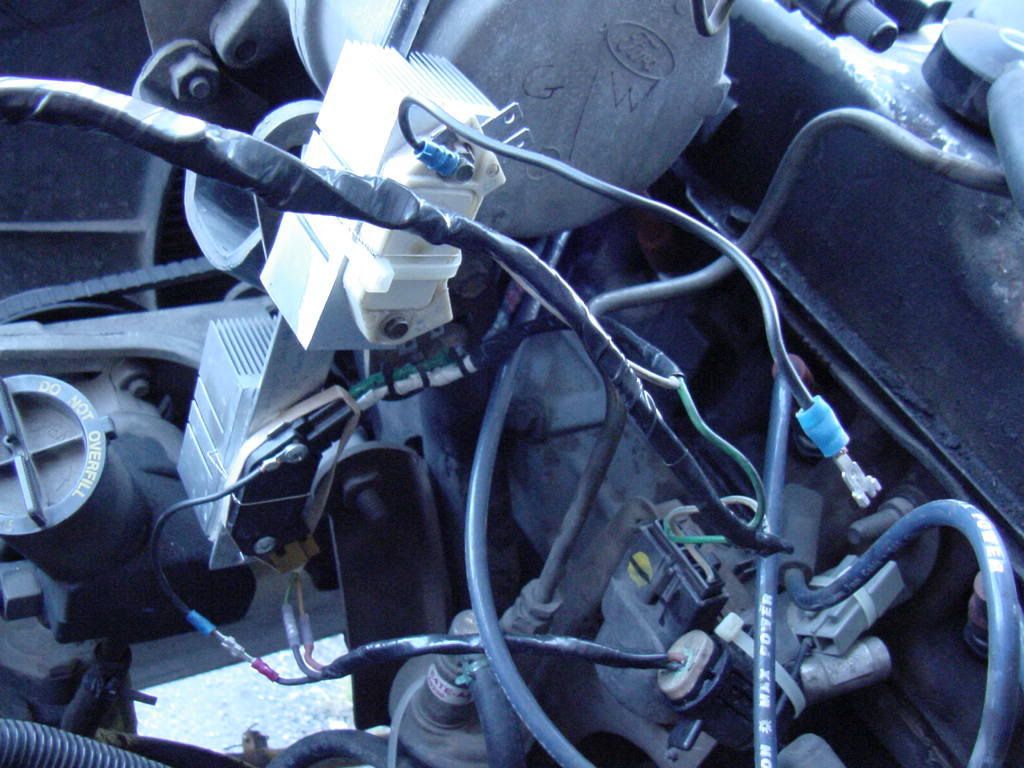
More info on the 4 pin module here, I mounted 2 of them to have a ride along spare IGN module.
http://www.carbdford.com/tech/HEI/hei.htm
The DS2 uses the older round coil.
I used the GM 4 pin module so I could keep the square coil currently on my truck.
More info on the 4 pin module here, I mounted 2 of them to have a ride along spare IGN module.
http://www.carbdford.com/tech/HEI/hei.htm
Thread Starter
|
Freshman User
Joined: Dec 2008
Posts: 35
Likes: 1
From: Arlington
Thanks a million for that link Jim. ive read about using the HEI ignition module but could find instructions for wiring it.
I hate to say it but even after following the directions its not working. it just keeps cranking. how do i go about troubleshooting this setup? im doubting the coil at this point. i messed something up in this adventure and it started smoking. wasnt a lot or for long but it might have been enough.
as far as i can see from your pictures, i have everything wired up the same as you. what are you using to power your coil? im using a wire from the 4 wire barrel connector (one wire goes to the oil pressure sending unit, one to the temp sending unit, other two are extra)
electrical problems have always been my weak spot, thats why i wanted to do this swap. learn best by jumping in the deep end
Trending Topics
Cargo Master
Joined: Mar 2008
Posts: 2,569
Likes: 207
From: Washington
Put a test light on the coil negative, the light should be on with the key ON and blink during cranking.
If the light is ON but doesn�t blink, check the GRD on the module, if your not sure add another GRD jumper wire. The 4 pin module is what makes the light blink, but only if it has a current path to GRD and a signal from the distributor magnetic pickup.
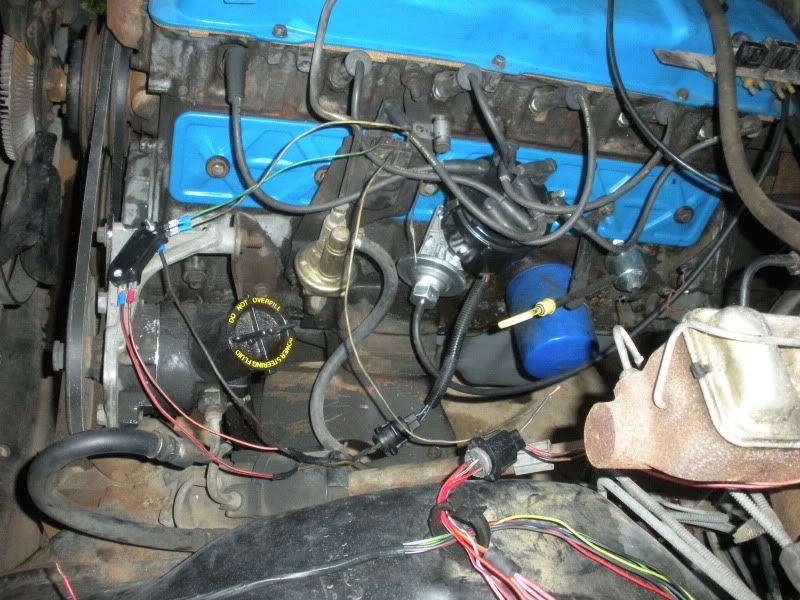
I used the fat red wire (firewall side of connector �color�) in the 4 pin connector. The 4th wire was not used and is shown coiled up in the photo. The Fat red wire was the resistor wire in my truck, you have a 50/50 chance on getting the resistor wire, both were hot with the key ON. I also powered the 4 pin module off the coil POS and it has been working fine this way.
I still think you might have a Grounding issue, check this first
If the light is ON but doesn�t blink, check the GRD on the module, if your not sure add another GRD jumper wire. The 4 pin module is what makes the light blink, but only if it has a current path to GRD and a signal from the distributor magnetic pickup.
I used the fat red wire (firewall side of connector �color�) in the 4 pin connector. The 4th wire was not used and is shown coiled up in the photo. The Fat red wire was the resistor wire in my truck, you have a 50/50 chance on getting the resistor wire, both were hot with the key ON. I also powered the 4 pin module off the coil POS and it has been working fine this way.
I still think you might have a Grounding issue, check this first
FTE Stories
Ford Trucks for Ford Truck Enthusiasts

Rezvani's Latest Post-Apocalytic Monster Is a Ford F-150 Raptor Underneath
Verdad Gallardo
Top 10 Most Expensive Ford Trucks Ever Sold on Bring a Trailer
Joe Kucinski
2027 Ford Super Duty Buyer's Guide (Every Model, Engine, & Package)
Brett Foote
Top 10 Ford Truck Tragedies
Joe Kucinski
AEV FXL Super Duty - the Super Duty Raptor Ford Doesn't Make
Brett Foote
Lobo Vs Lobo: Proof the F-150 Lobo Should Be Even Lower!
Michael S. Palmer
Ford's 2001 Explorer Sportsman Concept Looks For a New Home
Verdad Gallardo
10 Best Ford Truck Engines We Miss the Most!
Joe Kucinski
2026 Shelby F-150 Off-Road: Better Than a Raptor R?
Brett Foote
Thread Starter
|
Freshman User
Joined: Dec 2008
Posts: 35
Likes: 1
From: Arlington
ok i just got back from pokin around with my test light. this were all with the key on
coil positive to coil negative NO POWER
battery positive to coil negative NO POWER
battery ground to coil positive POWER
coil positive to distributor ground POWER
does this tell you anything? kinda make me think something is wrong with the coil but i think youre starting to notice i dont know what im doing when it comes to electrical lol
MSEE
Joined: Apr 2004
Posts: 10,386
Likes: 35
From: Austin, TX
You need to do the blinking test as described. Run a test light from the TACH TEST (negative) post of the coil down to ground, with the coil connected. Use clean, unpainted metal on the engine for ground. Use the key to crank the motor over, and the light should blink. Post your results.
Cargo Master
Joined: Mar 2008
Posts: 2,569
Likes: 207
From: Washington
ok i just got back from pokin around with my test light. this were all with the key on
coil positive to coil negative NO POWER
battery positive to coil negative NO POWER
battery ground to coil positive POWER
coil positive to distributor ground POWER
does this tell you anything? kinda make me think something is wrong with the coil but i think youre starting to notice i dont know what im doing when it comes to electrical lol
coil positive to coil negative NO POWER
battery positive to coil negative NO POWER
battery ground to coil positive POWER
coil positive to distributor ground POWER
does this tell you anything? kinda make me think something is wrong with the coil but i think youre starting to notice i dont know what im doing when it comes to electrical lol
coil shound be fine, press on
Thread Starter
|
Freshman User
Joined: Dec 2008
Posts: 35
Likes: 1
From: Arlington
Ok just did the blink test right. messed it up the first time cause i wasnt sure where to clamp the other end of the test light.
I used the engine ground toward the back of the block and put the test light on the negative side of the coil. light came on but didnt blink when i was cranking.
I think i should have jumped on the bad ground bandwagon as soon as Jim got on it.
So does this mean i need to work on my mounting bracket and getting a better ground for the module?
Cargo Master
Joined: Mar 2008
Posts: 2,569
Likes: 207
From: Washington
In my photo, the black wire on the far left is the ground. It is one of the 3 wires that go to the dist. and grounds inside the dist.
On my truck if I disconnect the "wrist lock connector" shown in the photo, the truck stops running. The module is still connect to a metal frame ground with screws and bolts/nuts so I was very suprised when it quit running. it really needs a good ground to run. If you have a long jumper wire you could run it to battery NEG for a test.
Jim
MSEE
Joined: Apr 2004
Posts: 10,386
Likes: 35
From: Austin, TX
The module grounds through the distributor. It does not ground through its mounting bolts, if that's the impression you are under. The ignition system grounding point is in the distributor; this is what the black wire in the distributor harness is for.
If the light does not BLINK, the module is not firing the coil. This could be for several reasons: no power to the module, bad module, module not getting a firing signal, or no coil power. We know you have power to the coil.
Let's start at the top; check for power to the module. Check power at the RED wire of the module with the key in RUN, you should have 12 volts. Check power at the WHITE wire of the module with the key in START, you should have 12 volts.
Thread Starter
|
Freshman User
Joined: Dec 2008
Posts: 35
Likes: 1
From: Arlington
I put one end on the test light on the battery negative and put the test light on both of the posts that connect to the coil had power. not sure if thats the right test.
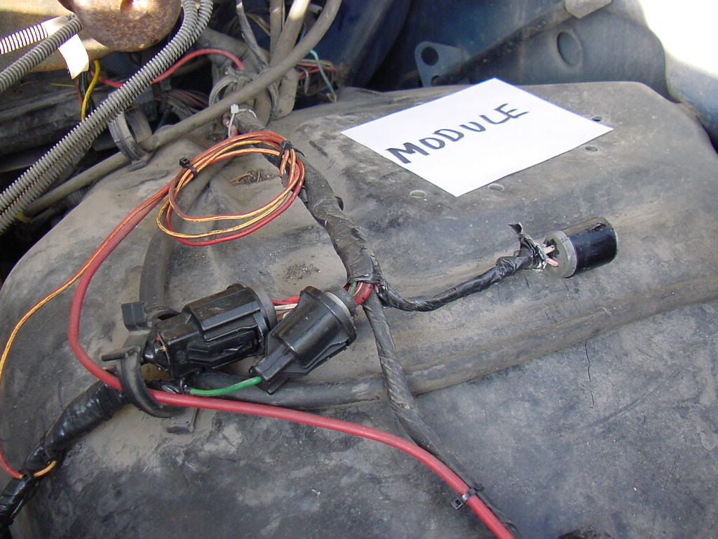
I took a few pics to help you guys out. hope they help some
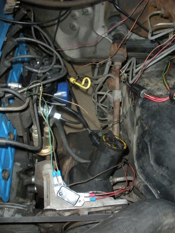
I took a few pics to help you guys out. hope they help some

