Heater circuit wiring
#1
Heater circuit wiring
'81 F100. I'm confused about the control wiring circuit. According to the '81 diagram, the Heater is on a CB, but mine is a 30A fuse. The wiring diagram shows an Orng wire going to a blower-switch terminal. It also shows a Brwn/White wire coming from the blower motor. Those 2 wires are noted going to the Fuse. I've always thought the blower control-switch was switching the Ground through the resistor pack. The resistor has a 3-wire connector for the Low/Med/High fan speeds from the blower switch and a 4th terminal which is direct-Ground. What is confusing me is the different color power wires that show to be coming from the same 30A fuse...1 to the blower-switch, the other coming from the fan-motor.
The '80 and earlier models have a circuit diagram that make sense, but the '81 doesn't, to me anyway.
Can someone clear this up for me? Thank you.
The '80 and earlier models have a circuit diagram that make sense, but the '81 doesn't, to me anyway.
Can someone clear this up for me? Thank you.
#4
#7
Join Date: Nov 2005
Location: Charles Town, W bygod Va
Posts: 7,437
Likes: 0
Received 3 Likes
on
3 Posts
Trending Topics
#8
I need to make a new wiring harness from the blower-switch to the resistor pak. That diagram is wrong so it's just as well it can't be read. I copied it from the Autozone site, where I made my mistake. It shows an Orange wire coming from the fuse to the blower switch.....that is wrong and what was confusing me. It should read as an Org/Blk wire going to the resistor pak and then controlling the blower speeds through the resistor pak grounding function. The motor power circuit goes to one terminal on the motor/through the AC function switch and to the fuse. That is what I always thought the control was, until I saw that AZ diagram...........mea culpa, y'all
#9
Join Date: Jul 2004
Location: Northern California
Posts: 8,786
Likes: 0
Received 18 Likes
on
17 Posts
That Diagram is indeed wrong.
This one isn't however. 1981 Heater wiring Diagram.

Black/Orange wire (Circut #181) comes off the fuse panel (F-14) 30 amp. Goes to the motor directly, (non-a/c) or to the a/c mode switch (A/C).
(A/C only) Brown/White wire (Circut #182) goes from a/c mode switch to blower motor positive side, but changes color at connector #606, to Brown/Orange wire (circut #181) before reaching the motor.
(A/C only) Brown/white wire (Circut #182) also splits and splices off at splice #603, and powers the a/c mode switch, for the A/C evaporative thermostat, the a/c clutch solenoid, and the carb solenoid (If Equipped) BEFORE the A/C mode switch.
(A/C only) Light Green/Purple hash wire. From the a/c mode switch, for switched power to the A/C evaporative thermostat, the a/c clutch solenoid, and the carb solenoid (If Equipped) AFTER the A/C mode switch.
The ground for the blower motor Orange/Black wire (Circut #261), is the one hooked between the blower switch and the blower motor resistor, and as you say. With the switch on high, this wire bypasses the resistor for High Speed.
Red/Orange hash, (Circut #260) is Low speed, (or medium low on a/c).
Light Blue/Orange hash (Circut #269) is medium, (or medium High on A/C)
The A/C blower resistor differes from the non-a/c and has four wires, and is permanetly grounded with a Black wire (Circut #57) for low speed, when the a/c mode switch is activated.
Hope this helps.
This one isn't however. 1981 Heater wiring Diagram.

Black/Orange wire (Circut #181) comes off the fuse panel (F-14) 30 amp. Goes to the motor directly, (non-a/c) or to the a/c mode switch (A/C).
(A/C only) Brown/White wire (Circut #182) goes from a/c mode switch to blower motor positive side, but changes color at connector #606, to Brown/Orange wire (circut #181) before reaching the motor.
(A/C only) Brown/white wire (Circut #182) also splits and splices off at splice #603, and powers the a/c mode switch, for the A/C evaporative thermostat, the a/c clutch solenoid, and the carb solenoid (If Equipped) BEFORE the A/C mode switch.
(A/C only) Light Green/Purple hash wire. From the a/c mode switch, for switched power to the A/C evaporative thermostat, the a/c clutch solenoid, and the carb solenoid (If Equipped) AFTER the A/C mode switch.
The ground for the blower motor Orange/Black wire (Circut #261), is the one hooked between the blower switch and the blower motor resistor, and as you say. With the switch on high, this wire bypasses the resistor for High Speed.
Red/Orange hash, (Circut #260) is Low speed, (or medium low on a/c).
Light Blue/Orange hash (Circut #269) is medium, (or medium High on A/C)
The A/C blower resistor differes from the non-a/c and has four wires, and is permanetly grounded with a Black wire (Circut #57) for low speed, when the a/c mode switch is activated.
Hope this helps.
#11
Heater/AC blower motor fuze
Yes this is wes and I don't know alot bout wiring.. on my 1981 ford f100 , after getting my truck back from shop they had to do bunch of work to it but after running the AC to make sure it was cold enough..The compressor was making the belt flap like it was loose but it was properly tight, too much current was being sent to fuze box and it melted the fuze into the fuze box.. I don't have any wiring diagrams and I have been searching on Google and no luck.. if anyone has a diagram can u email it too me at.. welowright@gmail.com. Also does anyone know what would cause that to happen? I haven't had any problems with it before.. thanks yaw and have a blessed day
#12
#13
Heater/AC blower motor fuze continued
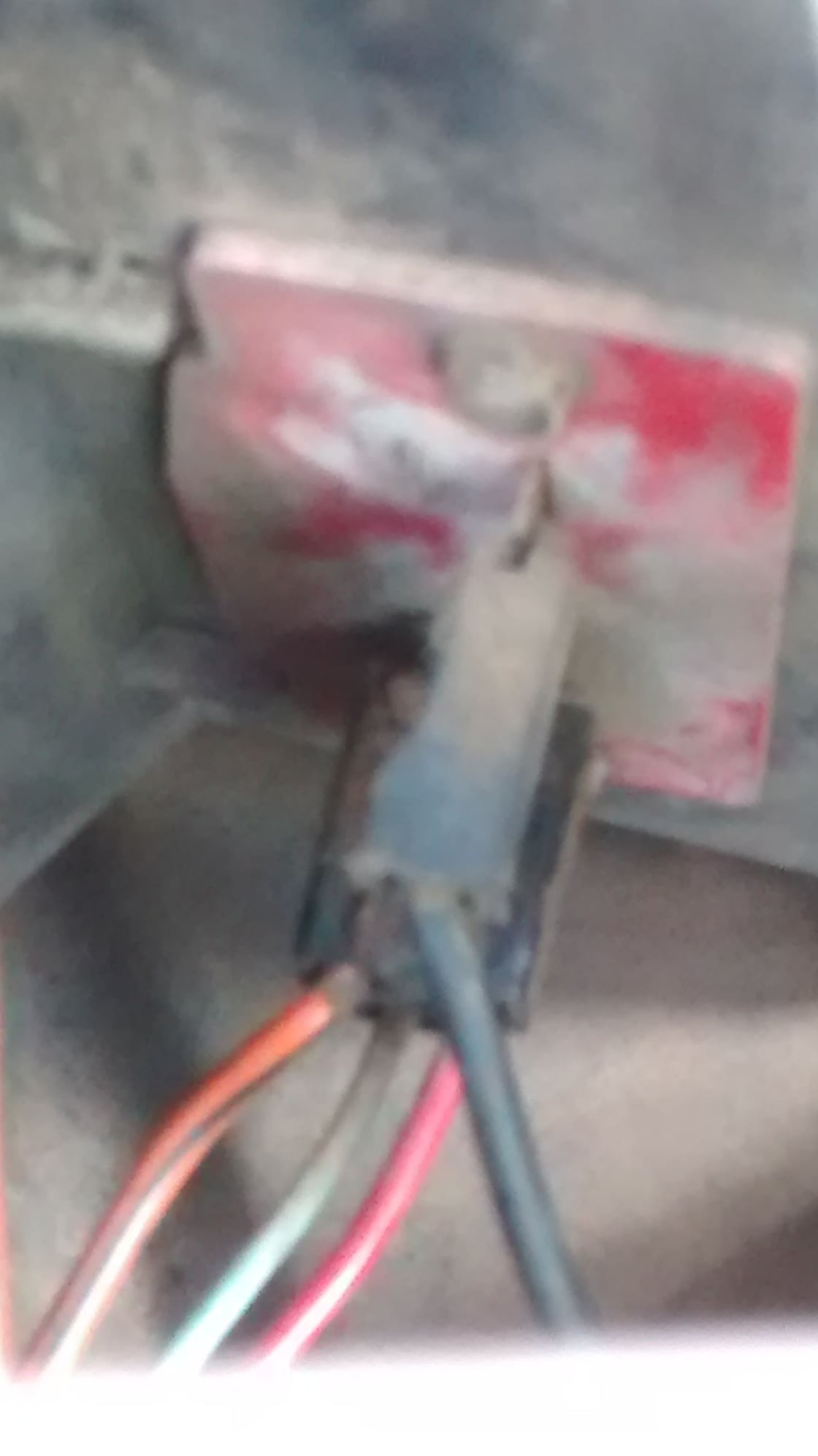
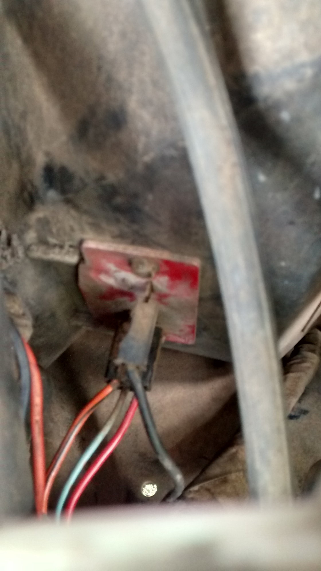
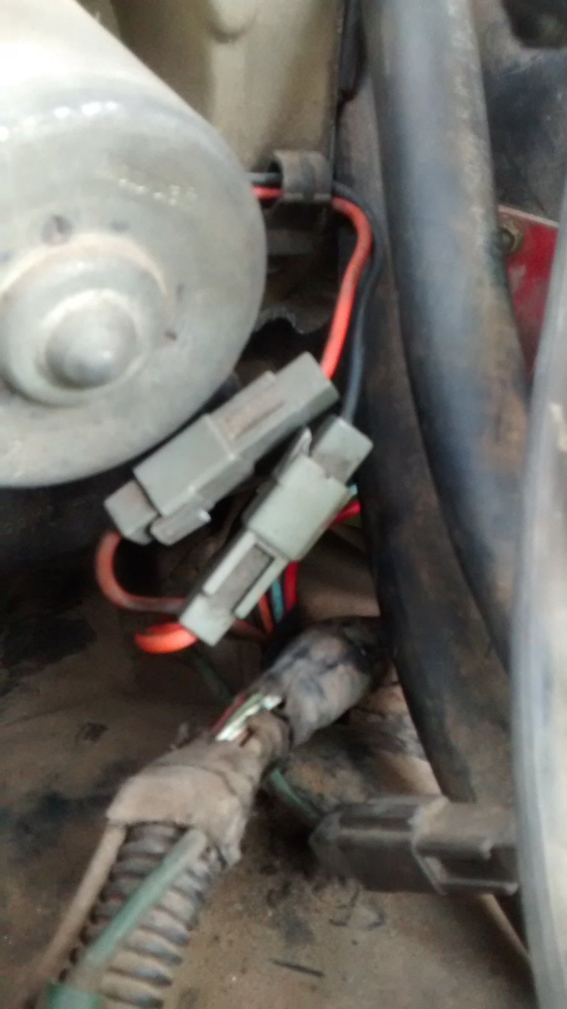
Hey this is wes .. thank you ArdWrknTrk I'll look at that.. does anyone have a 1981 ford f100 4.9 ltr with factory heat and ac , that can show me a picture of the blower motor where the wires connected to the prongs and the heater core box with the wires connected to the prongs please .. mine has upper prongs and lower prongs but the upper prong looks like one prong is cut flush .. does this all song proper for this model truck with factory AC and heat?? .. But it has only a single wire connector to it. I'll show pictures of mine later tonight..Thanks yaw
#14
Here is a link to the 1981 troubleshooting manual. 1981 EVTM - ???Gary's Garagemahal
You might find you will get a better response from the forum if you start your own thread with all the specific details of your own truck and issue instead of replying to an eight year old thread.
Pictures are always good.
The harness between motor and resistor block is different with a non-AC truck.
I usually find that the plug has melted or the resistor fuse has overheated, but I'm not quite sure what you are describing.
#15
Heater/AC blower motor fuze continued


