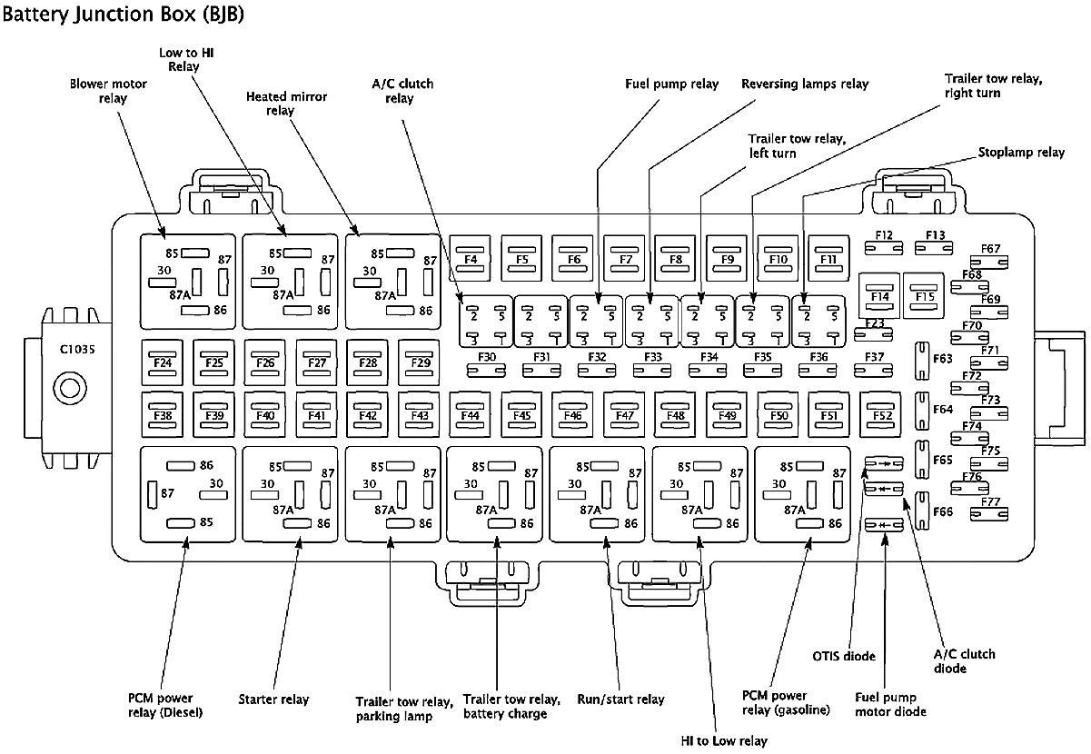
2008 F250 SD 5.4L CPS schematic
#1
2008 F250 SD 5.4L CPS schematic
I have a 2008 f-250 in my shop, and this truck is a nightmare. Please somebody, I have a client anxiously awaiting this truck and I can't find a schematic to save my soul. I need the diagram and a back-probing/testing method.
I need a schematic concerning the bank 2 CPS. The fuse-box in the engine compartment appears to have been exposed to muddy water. I repeatedly get codes for P0345 and P0349. Prior to that I was getting a "forced idle/reduced RPM" code, and another code concerning some sort of micro processor (P2107 and P2110). I cannot locate this so called processor. Another forum member says it's located inside the actual throttle body, however I have fully disassembled it and I cannot find this suspect chip whatsoever. I replaced the TPS and motor, the codes have not re-appeared thus far. I "re-learned/calibrated the throttle body" using the pedal depressed slowly and ignition on/off procedure.
I am not getting any power to the 5 volt reference circuit for the CPS. Fuses F74 and F30 were blown, replaced with no improvement. I believe the wiring harness or fuse box is damaged somehow causing the CPS circuit to fail.
The truck is running in limp mode. There is no power and I cannot get the RPM over 2500 as it bogs down terribly. All timing components including phasers and VCT solenoids replaced. Timing was confirmed correct 3 times. Throttle body has had the motor and TPS replaced. New plugs. New coils. CPS is new. Fuel pressure normal.
Does anybody have a pinout diagram? 2008 5.4L F250 SD 4x4, Canadian spec.
First man to help me out gets a 12 pack of beer Fed-Ex'd to his house.

#2

See the below link. F30 is for the AC clutch relay. When we purchased the truck part of the wiring harness was pinched between the valve cover and bank 1 head. That portion leads to the AC clutch and AC pressure switch. I can't see if it also leads to the crank sensor. The wires were crushed, melted together, and shorted to eachother, but not to the head because the split loom was sort of intact. So that explains F30 being blown...
F74 is for a TON of sensors.
Fuse F74 provides a reference circuit power to: VPWR: HEGO (heated exhaust gas O2 sensor), CMS ( unsure), MAFS (Mass air-flow sensor), EVMV (electric vapor management valve), CMCV (flaps in the intake manifold like a butterfly valve), VCT (variable camshaft timing solenoids) , IMTV (intake manifold tuning valve)
Gee... I wonder why the truck's in limp mode?
Gee... I wonder why the truck's in limp mode?
https://www.manualslib.com/manual/53...age=277#manual
Update: fuse F74 is getting power to it. I traced the 5volt reference wires to the PCM. I made a jumper wire from the PCM to the sensor to eliminate a bad wiring harness connection, ran the truck, and saw the 5 volt circuit fluctuate from 5.0v down to less than 1.0v about every 10 seconds. I though that circuit is supposed to be at 5.0v at all times? Does that mean the PCM is toast?
How do I tell if the PCM needs to be replaced?
Thread
Thread Starter
Forum
Replies
Last Post
BigHazard
1999 - 2003 7.3L Power Stroke Diesel
2
02-21-2007 07:49 AM
Ghost24
1999 - 2003 7.3L Power Stroke Diesel
5
12-23-2005 09:12 PM


