When you click on links to various merchants on this site and make a purchase, this can result in this site earning a commission. Affiliate programs and affiliations include, but are not limited to, the eBay Partner Network.
Was wondering if I could get the schematics tryed the link will not let me see them my email is kevinignash@gmail.com if so ty truck just started shutting down on me that's the only code coming up
Hi Rockledge, thanks for your support on this thread over the years; the insight on alternatives have been handy.
Do you still have the original schematic handy? The share that was once hosted no longer works, and i'd like to take a stab at making my own before paying 100$ for an emulator. Or would someone else be nice enough to send or host it?
I've looked long and hard for it, but I cannot find a copy saved on my computer.
Unfortunately, all the files that I had previously posted to that host site were wiped out when Comcast/Xfinity suddenly decided to stop offering file-sharing services as part of my subscription.
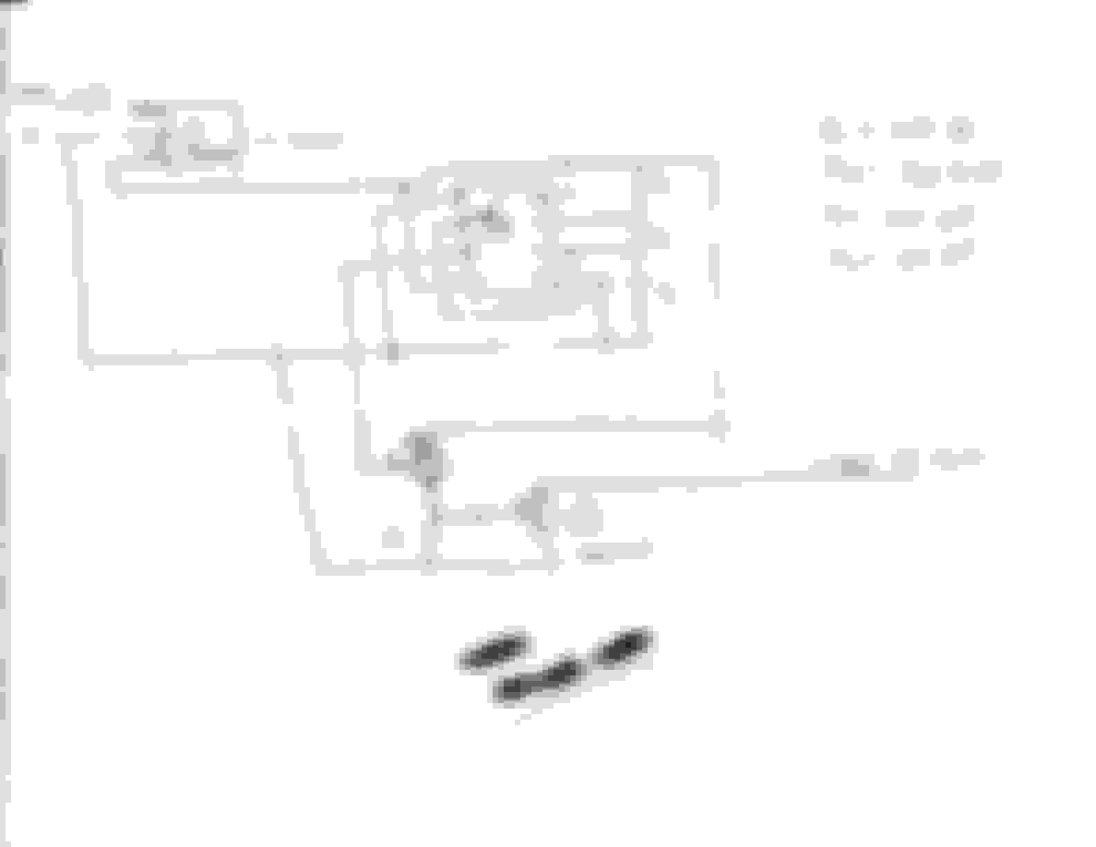
Someone saw this old thread and emailed me. I found the Diagram from years ago that was from a forum member, i think it was ToeHead. I will post it as soon i figure out how to post a PDF file to the thread.
Here is the file. I got this from forum member ToeHead many years ago, I got the parts from a local electronics store, made it on a breadboard and tried it , it worked. I tried making a permanent one, but my soldering skills were lacking. So i stuck the breadboard under the seat in the truck and it has been there ever since.
Here is the file. I got this from forum member ToeHead many years ago, I got the parts from a local electronics store, made it on a breadboard and tried it , it worked. I tried making a permanent one, but my soldering skills were lacking. So i stuck the breadboard under the seat in the truck and it has been there ever since.
Hey Mark, looks like it didn't go through. Could you try again, or maybe just email me directly above and I could try my hand at uploading it for everyone?
Edit: For some reason it shows up on mobile fine, but not in my browser.. hmm, oh well. Thanks for uploading it. I think i'll do the diagram up a bit and repost. Thanks!
Hi Folks,
New member here, and pulling up an ancient thread...
My 99 Ranger started knocking hard, acting seriously advanced, and things are pointing this direction. I managed to find a tankful of flex fuel yesterday about an hour from home (I think it was around E50). I could not make it ping, up and down the grades through the national forest, wrong gears, whatever, solid as a rock with the pedal on the floor where on E10 I was nursing hills at part throttle and slowing down.
I have the emulator, version 1 soldered up and I'm up to the pair of PNP transistors that have been added to the schematic above. I'm either missing the specs or it doesn't matter. Is there a best PNP transisitor to use here?
Sooo, y'all are electronics geniuses too I looked up a couple transistors and used a pair of 2N3906 PNP transistors. I'll post if it fails or after it has run a bit. Plumbing, I can solder some copper pipe. I had reading glasses and a lighted magnifying glass going to see to
solder this stuff . To get the 5.6k ohms I had to put 3 resistors in series to add up to 5.6K , that's why there is a bank of them on my board compared to the schematic.
I pulled a trailer with lumber on it home today and gained respectable speed on a ~10% grade, an empty trailer was like flogging a dying mule last week. It is definitely set up to run on E85 currently, its actually kind of badass on moonshine, for a 3.0.
Well , that was a fail. The truck ran great on E85. Had no serious pings with premium and was thrashing on E10. I plugged in that emulator and it barely ran, would not idle, erratic... no go. Simply unplugged it ran about the same so I'm guessing the computer is just kicking out the signal. I slapped together a quick oscilloscope using an arduino and the computer monitor. I'm well over my head but I think I have the blue square wave notches set to 4milliseconds. I think the heartbeat is out of time.
I started building again and looked at the hand drawn schematic compared to the one I built from, the pretty schematic above. Look at the values of the capacitors. Either I'm not understanding, or the large capacitor has been changed between sketches... ?
This Hennessey Takes the Expedition Tremor's Off-Roading Capability to the Next Level
Slideshow: The VelociRaptor Expedition gains a lift, upgraded suspension, Brembo brakes, and trail-ready equipment while retaining the stock 440-horsepower EcoBoost V6.
Rezvani's Latest Post-Apocalyptic Monster Is a Ford F-150 Raptor Underneath
Slideshow: Called the Fortress, the 850-horsepower pickup combines Raptor underpinnings with military-inspired features, survival equipment, and a starting price of $285,000.


 . To get the 5.6k ohms I had to put 3 resistors in series to add up to 5.6K , that's why there is a bank of them on my board compared to the schematic.


