1983 - 2012 Ranger & B-Series All Ford Ranger and Mazda B-Series models

Flex-Fuel Sensor Technical Info

Thread Tools
 
Search this Thread
 
  #1  
Old 04-06-2008, 04:27 PM
SpikedCola's Avatar
SpikedCola
SpikedCola is offline
New User
Thread Starter
Join Date: Apr 2008
Posts: 7
Likes: 0
Received 0 Likes on 0 Posts
Flex-Fuel Sensor Technical Info

Ive been searching around, trying to come up with some info on the sensor. There arent any wrecking yards around here that have one, nor do I know anyone who has a working one on their truck (doing this for a friend - 2000 Ford Ranger w/ FlexFuel capabilities).

I know there are +12v, GND, and Signal lines - Im interested in the signal line. Id like to build an emulator for the sensor, as the truck will only ever be run on 87 octane. I need to send 40-60Hz (will try 40Hz for now, and scale it up if I need to) to the ECU, but what kind of signal was originally sent by the FFS? Square wave? Sinusoidal? What voltage, p-p was it?

If anyone can answer my questions it would be a huge help.
 
  #2  
Old 04-06-2008, 06:20 PM
Rockledge's Avatar
Rockledge
Rockledge is offline
Post Fiend
Join Date: Jan 2003
Location: Connecticut
Posts: 9,748
Likes: 0
Received 12 Likes on 12 Posts
Welcome. Check this thread out, maybe it'll help: https://www.ford-trucks.com/forums/6...uel-gurus.html
 
  #3  
Old 04-06-2008, 06:46 PM
SpikedCola's Avatar
SpikedCola
SpikedCola is offline
New User
Thread Starter
Join Date: Apr 2008
Posts: 7
Likes: 0
Received 0 Likes on 0 Posts
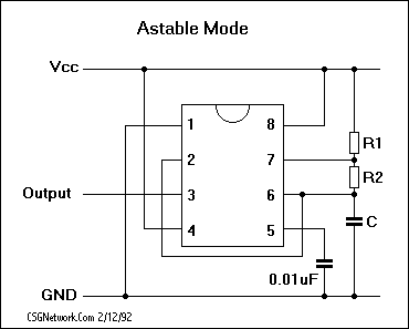
Ahh, thats exactly what I needed! Doesnt even look hard. Just need a 555 in astable mode running around 57Hz sinking the Signal line.
 
  #4  
Old 04-06-2008, 07:00 PM
Rockledge's Avatar
Rockledge
Rockledge is offline
Post Fiend
Join Date: Jan 2003
Location: Connecticut
Posts: 9,748
Likes: 0
Received 12 Likes on 12 Posts
Go for it! Keep us posted on your progress. Good luck.
 
  #5  
Old 04-07-2008, 03:15 AM
WA1986F-250's Avatar
WA1986F-250
WA1986F-250 is offline
Senior User
Join Date: Jan 2005
Posts: 141
Likes: 0
Received 1 Like on 1 Post
Early GM FFVs that had the fuel ratio sensor sent square waves. Voltage if I remember correctly was 5v.
 
  #6  
Old 04-09-2008, 11:27 PM
SpikedCola's Avatar
SpikedCola
SpikedCola is offline
New User
Thread Starter
Join Date: Apr 2008
Posts: 7
Likes: 0
Received 0 Likes on 0 Posts
WARNING: I havent bread-boarded this circuit yet, it was all done in a sim, so test it before you build it. Also, I didnt include it in the picture, but 555 chips are labelled like this:

8 7 6 5
-------
N -----
-------
1 2 3 4

where N is the little notch in the side.


  #7  
Old 04-10-2008, 08:51 AM
Rockledge's Avatar
Rockledge
Rockledge is offline
Post Fiend
Join Date: Jan 2003
Location: Connecticut
Posts: 9,748
Likes: 0
Received 12 Likes on 12 Posts
Double post
 

Last edited by Rockledge; 04-10-2008 at 08:54 AM. Reason: Double post
  #8  
Old 04-10-2008, 08:51 AM
Rockledge's Avatar
Rockledge
Rockledge is offline
Post Fiend
Join Date: Jan 2003
Location: Connecticut
Posts: 9,748
Likes: 0
Received 12 Likes on 12 Posts
Cool! But I have to admit that your schematic is kinda going right over my head.

I'm not sure I'm fully grasping things, so could you elaborate a little bit? For example, what do the labels mean (Vin, dis, ctl, ...)? And what are "E", "B", and "C"?
 
  #9  
Old 04-10-2008, 12:12 PM
Pablo-UA's Avatar
Pablo-UA
Pablo-UA is offline
Post Fiend
Join Date: Oct 2005
Location: Kiev, Ukraine
Posts: 5,242
Likes: 0
Received 0 Likes on 0 Posts
And what are "E", "B", and "C"? Emmiter, Collector and Base - terminals of P-N-P transistor used like electronic switch with "common collector". It is made in TO-39 ore SOT-223 body. Usually black. TO-39 body you can see at picture.

Vin - voltage in, ctl - controll....

Well, my opinion... I guess stock sensor generates other then square punses, but I think square pulses generator will work fine.
 
  #10  
Old 04-10-2008, 12:14 PM
Pablo-UA's Avatar
Pablo-UA
Pablo-UA is offline
Post Fiend
Join Date: Oct 2005
Location: Kiev, Ukraine
Posts: 5,242
Likes: 0
Received 0 Likes on 0 Posts
I'd like to make it ajustable. If you can hear nocking sound you can ajust timong. I added nock sensor to my EEC-IV aero but when I have detonation SPOUT line automaticly brakes.... Primitive, but works fine....
 
  #11  
Old 04-10-2008, 03:11 PM
SpikedCola's Avatar
SpikedCola
SpikedCola is offline
New User
Thread Starter
Join Date: Apr 2008
Posts: 7
Likes: 0
Received 0 Likes on 0 Posts
Originally Posted by Rockledge
Cool! But I have to admit that your schematic is kinda going right over my head.

I'm not sure I'm fully grasping things, so could you elaborate a little bit? For example, what do the labels mean (Vin, dis, ctl, ...)? And what are "E", "B", and "C"?
The labels arent really important - the numbers on the outside of the chip are the pin numbers, the labels are just there so you dont need to reference a datasheet to know what pin does what. But if youre wondering:

1 - gnd - Ground, low level
2 - tr - A short pulse high -> low on the trigger starts the timer
3 - output - During a timing interval, the output stays at +Vin
4 - R - A timing interval can be interrupted by applying a reset pulse to low (0V)
5 - Ctl - Control voltage allows access to the internal voltage divider (2/3 Vin)
6 - th - The threshold at which the interval ends (ends if thr -> 2/3 Vin)
7 - dis - Connected to a capacitor whose discharge time will influence the timing interval
8 - Vin - The positive supply voltage which must be between 5 and 15 V, high level

E - Emitter
B - Base
C - Collector
All three reference pins on a BJT transistor (in this case, a PNP one). The emitter is where current emits (flows out from), the collector is where current collects (comes into) and the base is the metaphorical "switch" that lets current flow (like a light switch - on and off).


I'd like to make it ajustable. If you can hear nocking sound you can ajust timong. I added nock sensor to my EEC-IV aero but when I have detonation SPOUT line automaticly brakes.... Primitive, but works fine....
While its a good idea, the problem with it being adjustable on-the-fly is that changing just R1 or R2 change the length of the pulse (ex. right now its on for an almost equal amount of time - but if you change just R1 or just R2, it may be "on" for 2x - 3x longer than it is "off"). The best way to do it would be to vary the capacitor - smaller values will increase the frequency, bigger values will decrease the frequency - but it is pretty hard to find variable capacitors in the uF range.

If you find that 57Hz is too low, and wanted to make it higher, use this calculator:
555 Timer Calculator
Sub in 4.7 and 10 for R1 and R2 (if you want - I picked those because they are common values) and play around with the capacitor's value to adjust the frequency.


I will prototype this tonight after work and take a few pictures, in case the schematic is confusing (Im sure it is if you dont work with them all the time). This one should be a bit easier (this one shows the actual chip layout and how you could route the wires):
 
  #12  
Old 04-10-2008, 08:33 PM
SpikedCola's Avatar
SpikedCola
SpikedCola is offline
New User
Thread Starter
Join Date: Apr 2008
Posts: 7
Likes: 0
Received 0 Likes on 0 Posts
Looks like the link to the pic I was trying to host is broken. "This one should be a bit easier:"
 
  #13  
Old 04-11-2008, 03:45 PM
Pablo-UA's Avatar
Pablo-UA
Pablo-UA is offline
Post Fiend
Join Date: Oct 2005
Location: Kiev, Ukraine
Posts: 5,242
Likes: 0
Received 0 Likes on 0 Posts
My friend drow old Soviet RAF van, he used to open engine cover and ajust ign. timing on-the-fly turning distibutor.... I used to do it in my aero but when I stopped on red only....
 
  #14  
Old 04-11-2008, 10:30 PM
SpikedCola's Avatar
SpikedCola
SpikedCola is offline
New User
Thread Starter
Join Date: Apr 2008
Posts: 7
Likes: 0
Received 0 Likes on 0 Posts
Woohoo, it works. I think. Going to swing by my uncle's tomorrow and scope the output, see if it is actually ~57Hz or not. Decided to try out my cellphone's macro mode, so here's a snapshot of the breadboard'd circuit:
 
  #15  
Old 04-29-2008, 09:24 PM
Rockledge's Avatar
Rockledge
Rockledge is offline
Post Fiend
Join Date: Jan 2003
Location: Connecticut
Posts: 9,748
Likes: 0
Received 12 Likes on 12 Posts
Originally Posted by SpikedCola
Woohoo, it works. I think. Going to swing by my uncle's tomorrow and scope the output, see if it is actually ~57Hz or not. Decided to try out my cellphone's macro mode, so here's a snapshot of the breadboard'd circuit:
So how's it working out so far?


Quick Reply: Flex-Fuel Sensor Technical Info


All times are GMT -5. The time now is 01:54 PM.